Dupa plasarea solicitării de comandă, in sectiunea Istoric puteti vedea cate solicitări de comandă mai avem de procesat inaintea dumneavoastra
Program de lucru: Luni - Vineri 9:00 - 18:00, pauza 13:00 - 14:00.
Se efectueaza lucrari de mentenanta la site si pot aparea erori. In cazul in care intampinati erori va rugam sa reincercati mai tarziu.
Ridicarea personala este disponibila pentru comenzile achitate in avans. Se pot ridica dupa ce sunt pregatite.
WOOW !!! Livrare gratuita la locker Easybox pentru comenzi mai mari de 98 RON !
No products
 View larger


FPF1320 Multiplexer with Micro-B USB Connector
0104110000010636
New product
This breakout board for Fairchild’s FPF1320 acts as a power multiplexer, allowing you to select which of two power sources is connected to a load while blocking reverse current into either of the sources. It handles up to 1.5 A of current at 1.5 V to 5.5 V and also breaks out a USB Micro-B connector that can be used to supply one of the input power rails.
See description for more details about the product.
Add to cart now!
This product is no longer in stock
- Write a review
- Remove this product from my favorite's list.
- Add this product to my list of favorites.
More info
Overview
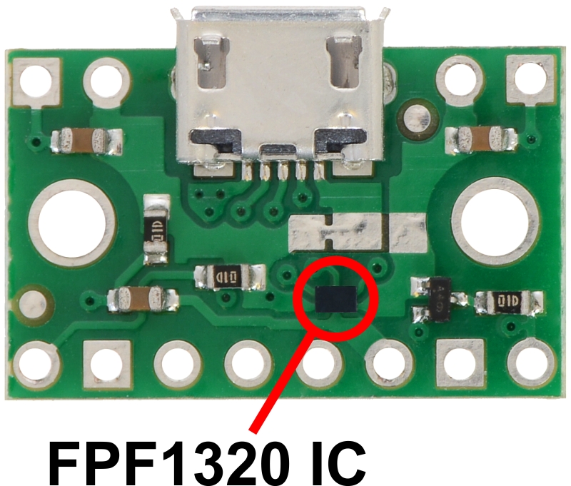
The Fairchild FPF1320 dual-input single-output power switch is a unique IC that switches a load between two power sources. It behaves as a power multiplexer (or mux), using a digital select signal to determine which of the two 1.5 V to 5.5 V input power rails to connect to the output, and can handle a maximum of 1.5 A while blocking unwanted reverse current from flowing from output to input or between inputs. Each input channel is controlled by an internal MOSFET switch, avoiding the voltage drop that occurs when diodes are used to OR multiple power supplies together.
However, the FPF1320 is only available in a tiny 1 mm x 1.5 mm BGA (ball grid array) package, making it difficult for a student or hobbyist to use. To address that issue, this board mounts the chip onto a compact carrier with 0.1" pin spacing that makes it easy to use with standard solderless breadboards, and it also serves as a breakout for a USB Micro-B connector that can be used to supply one of the input power rails.
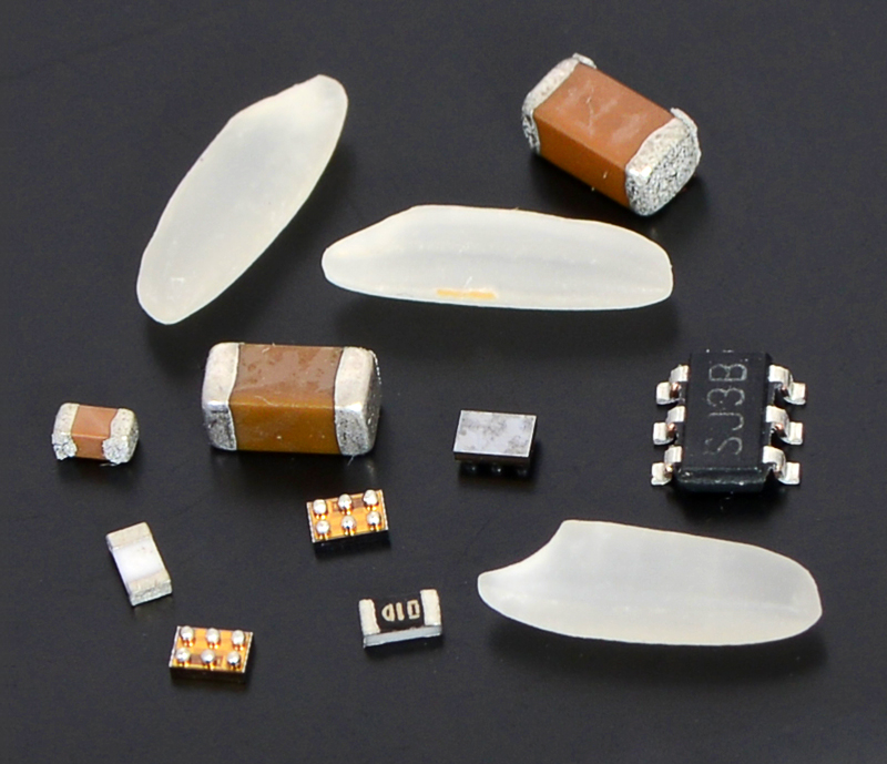
Three FPF1320 BGA parts (two with solder balls facing up) among grains of rice and components in 0603, 1206, and SOT-23 packages.
The board is configured so that the "B" power rail is preferred and will be selected by default when that power source is present. USB power is connected to this preferred rail, so the default behavior is for the board to select USB power when USB is connected and the alternate "A" power rail when it is not. This enables the common application of having a device that can be powered by USB or an external power supply, automatically choosing the appropriate source based on what is connected. The default behavior can be changed through a surface-mount jumper and overridden through the power select (SEL) input.
Since this board is a carrier for the FPF1320, we recommend careful reading of the FPF1320 datasheet (1MB pdf).
We carry a similar power multiplexer based on the TPS2113A that offers some additional features, including automatic switching with minimal voltage droop, a configurable switching threshold, and configurable current limiting.
Using the power multiplexer
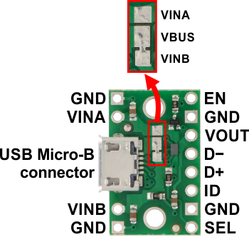
Pinout
| Pin | Description |
| VINA | Power supply input A. Can be connected to a 1.5 V to 5.5 V power source. |
| VINB | Power supply input B. Can be connected to a 1.5 V to 5.5 V power source. Connected to VBUS by default through surface-mount jumper. This power rail is preferred by default. |
| VBUS | USB 5 V supply. Connected to VINB by default through surface-mount jumper. |
| VOUT | Multiplexed power output. |
| GND | Common ground for power supplies, load, and USB. (All of the board’s GND pins are internally connected with each other and with GND from the USB connector.) |
| SEL | Select input that determines which power source is selected: LOW (< 0.65 V) selects VINA, HIGH (> 1.15 V) selects VINB. On-board pull-up resistor to VINB gives it the default behavior of selecting VINB when VINB is connected and selecting VINA when it is not. |
| EN | Enable input; when driven low, disconnects VOUT from both VINA and VINB. Pulled high through a pull-up resistor and diodes to both VINA and VINB so the IC is enabled by default whenever either power supply is present. |
| D- D+ ID |
Signals broken out from USB connector. |
Control inputs
The FPF1320 has two control inputs that can optionally be used to override the default behavior of the device: SEL (power select) and EN (enable).
The SEL pin determines which power input rail is connected to the output: logic low (< 0.65 V) on SEL connects VINA to VOUT, while logic high (> 1.15 V) on SEL connects VINB to VOUT. The board pulls SEL to VINB by default, so a suitable voltage on VINB will cause it to be selected as the power source regardless of whether VINA is present, making it the preferred power source. When VINB is not present, the SEL pin is pulled low by default and VINA is automatically selected. Externally driving the SEL pin will override this default behavior.
Because of the way the board connects SEL by default, the output voltage will briefly drop to the logic level threshold of the SEL pin (about 1 V) when the multiplexer is transitioning from the VINB source to the VINA source. The “Power source selection” section below discusses this behavior in more detail, as well as some possibilities for modifying it.
The EN pin can be driven low to turn off the output and put the FPF1320 in a low-power state. The board pulls EN high through a 100 kΩ pull-up resistor and a pair of diodes to both VINA and VINB, so it is enabled by default when a suitable voltage is present on either input.
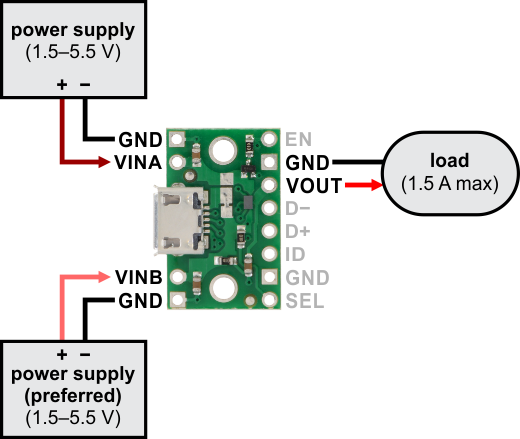
Power connections without USB
If you want to select from between two general power supplies, you can connect one power source across VINA and GND and the other across VINB and GND. The voltages on these power inputs should be between 1.5 V and 5.5 V. The load should be connected across VOUT and GND and should draw no more than 1.5 A. In this configuration, the "B" power supply is preferred and connected to the output by default when it is present.
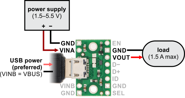
Power connections with USB
The Micro-B USB connector makes it easy to use USB as one of the two power sources. By default, the VBUS line from the USB connector is tied to VINB. This allows you to power your circuit from either USB or an external power source connected to VINA, with USB as the preferred power source.
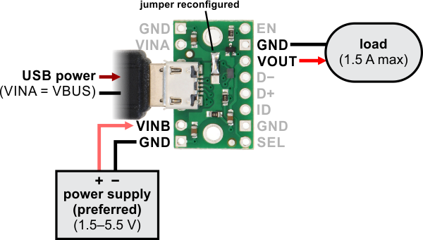
If you want the external source to be preferred instead of USB, you can use a hobby knife to cut the trace in the board’s surface-mount jumper that connects the VINB and VBUS pads, then bridge the VBUS and VINA pads to connect those two lines together. You can then connect your external source to VINB, making it the preferred supply.
Warning: It is important to be aware that while this board has three power inputs, two of those three are typically tied together (there are only two independent power inputs to the FPF1320). As such, you must take care to avoid creating a short circuit between USB power and an external power supply. For example, when the board is in its default configuration (i.e. with VBUS tied to VINB), any external power supply must be connected to VINA; connecting it to VINB will create a short between this power supply and USB power when USB is connected.
The remaining lines from the USB connector (D−, D+, ID, and GND) are broken out to a set of pins adjacent to VOUT, allowing this module to also function as a basic USB Micro-B connector breakout board.
Power source selection
The FPF1320 itself is capable of seamlessly transitioning between sources when the logic level of the SEL signal changes. However, since the board pulls SEL to VINB by default, the multiplexer will not select the VINA source when the VINB source is disconnected until VINB falls to the threshold at which the SEL state changes (somewhere between 0.65 V and 1.15 V). Since VOUT is supplied by VINB until then, it will also fall by the same amount, which can be a problem if the load normally operates at a higher voltage and cannot tolerate a drop to 1 V. (For example, the load might be a 5 V microcontroller that undergoes a brown-out reset if its supply voltage falls below 2.7 V.)
To avoid such a pronounced drop when switching from VINB to VINA, you can bias the voltage on SEL. The board connects SEL to VINB through a 100 kΩ resistor, so adding a resistor between SEL and GND creates a voltage divider that lowers the SEL voltage and in turn causes the board to switch sooner. For example, adding a 30 kΩ resistor between SEL and GND lowers SEL to about 1.15 V when VINB is 5 V, and in our tests, it caused the FPF1320 to switch over to VINA as soon as VINB fell to about 4 V.
Note that the SEL input does not have a precision threshold, so even this method might be unsuitable for especially voltage-sensitive applications. In such cases, the selection behavior can be overridden by directly connecting a digital signal (such as an output from a comparator or a microcontroller monitoring VINB) to the SEL pin.
Schematic diagram
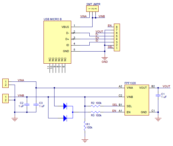
This schematic is also available as a downloadable PDF (156k pdf).
Specifications
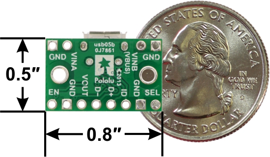
Dimensions
| Size: | 0.8" x 0.55" x 0.15"1 |
| Weight: | 0.8 g2 |
General specifications
| Minimum operating voltage: | 1.5 V |
| Maximum operating voltage: | 5.5 V |
| Maximum output current: | 1.5 A |
Notes:
1 Without included optional headers. This measurement includes the USB Micro-B connector, which extends 0.05" past the edge of the PCB.
2 Without included optional headers.
Don't delay. Buy today.
Add to cart now!
Reviews
Customers who bought this product also bought:
-
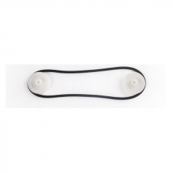
19 mm...
19 mm Conveyor Belt See description for more...
1,49 lei
-
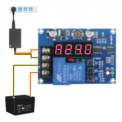
Battery...
Battery Charge Controller Module with...
29,99 lei
-
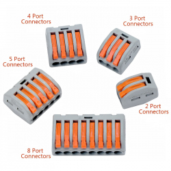
PCT-8-118...
PCT-8-118 Wire Connector See description for...
3,42 lei
-
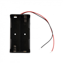
2xR6 Battery...
This battery holder making it convenient for...
1,99 lei
-

Plastic Box...
Ideal for storing thread, buttons and bobbins....
14,99 lei
-

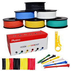
Plusivo...
22 Gauge Hook up Stranded Wire Kit: It includes...
50,00 lei
-
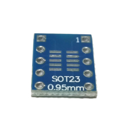
SOT23,...
The product is an adapter for SOT23, MSOP10 and...
0,63 lei
-
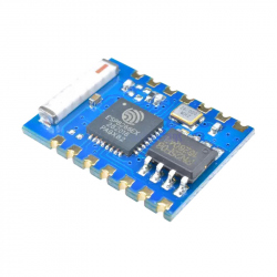
ESP-03 WiFi...
This is a highly integrated mini Wi-Fi module...
29,95 lei
-
Plusivo...
24 Gauge Hook up Stranded Wire Kit: It includes...
50,00 lei
-
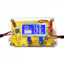
Variable...
Useful adjustable low voltage power supply to...
49,99 lei