Dupa plasarea solicitării de comandă, in sectiunea Istoric puteti vedea cate solicitări de comandă mai avem de procesat inaintea dumneavoastra
Program de lucru: Luni - Vineri 9:00 - 18:00, pauza 13:00 - 14:00.
Se efectueaza lucrari de mentenanta la site si pot aparea erori. In cazul in care intampinati erori va rugam sa reincercati mai tarziu.
Ridicarea personala este disponibila pentru comenzile achitate in avans. Se pot ridica dupa ce sunt pregatite.
WOOW !!! Livrare gratuita la locker Easybox pentru comenzi mai mari de 98 RON !
No products
") View larger
View larger
")
")
")
")
")
")
")
")
AltIMU-10 v4 Gyro, Accelerometer, Compass, and Altimeter (L3GD20H, LSM303D, and LPS25H Carrier)
0104110000010803
New product
The Pololu AltIMU-10 v4 is an inertial measurement unit (IMU) and altimeter that features the same L3GD20H gyro and LSM303D accelerometer and magnetometer as the MinIMU-9 v3, and adds an LPS25H digital barometer.
See description for more details about the product.
Add to cart now!
This product is no longer in stock
- Write a review
- Remove this product from my favorite's list.
- Add this product to my list of favorites.
More info
Overview
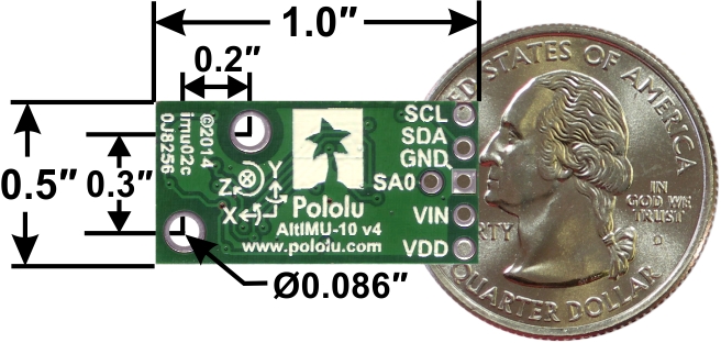
The Pololu AltIMU-10 v4 is a compact (1.0" x 0.5") board that combines ST’s LPS25H digital barometer, L3GD20H 3-axis gyroscope, and LSM303D 3-axis accelerometer and 3-axis magnetometer to form an inertial measurement unit (IMU) and altimeter; we therefore recommend careful reading of the LPS25H datasheet (1MB pdf), L3GD20H datasheet (3MB pdf), and LSM303D datasheet (1MB pdf) before using this product. These sensors are great ICs, but their small packages make them difficult for the typical student or hobbyist to use. They also operate at voltages below 3.6 V, which can make interfacing difficult for microcontrollers operating at 5 V. The AltIMU-10 v4 addresses these issues by incorporating additional electronics, including a voltage regulator and a level-shifting circuit, while keeping the overall size as compact as possible. The board ships fully populated with its SMD components, including the L3GD20H, LSM303D, and LPS25H, as shown in the product picture.
The AltIMU-10 v4 features a newer pressure sensor than its predecessor, the AltIMU-10 v3, enabling pressure and altitude measurements with higher accuracy and lower noise, but the two boards are otherwise identical. Compared to the original AltIMU-10, the v4 version offers a number of improvements arising from the use of newer MEMS sensors, including a wider maximum magnetic sensing range and better gyroscopic accuracy and stability. This version also adds a pin for changing the sensor slave addresses, allowing two AltIMUs to be on the same I2C bus.
The AltIMU-10 v4 is pin-compatible with both the v3 version and the original AltIMU-10, but changes in I2C addresses and configuration registers might require some changes to software written for the older version (this should not be an issue if you are using our Arduino libraries). It is also pin-compatible with the MinIMU-9 v3 and offers the same functionality augmented by a digital barometer that can be used to obtain pressure and altitude measurements. It includes a second mounting hole and is only 0.2" longer than the MinIMU-9 v3. Any code written for the MinIMU-9 v3 should also work with the AltIMU-10 v4.
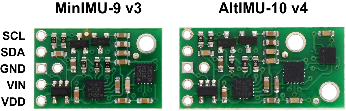 Side-by-side comparison of the MinIMU-9 v3 with the AltIMU-10 v4.
The LPS25H, L3GD20H, and LSM303D have many configurable options, including selectable resolutions for the barometer and dynamically selectable sensitivities for the gyro, accelerometer, and magnetometer. Each sensor also has a choice of output data rates. The three ICs can be accessed through a shared I2C/TWI interface, allowing the sensors to be addressed individually via a single clock line and a single data line. Additionally, the SA0 pin is accessible, allowing users to change the slave addresses and have two AltIMUs connected on the same I2C bus (For additional information, see the I2C Communication section below).
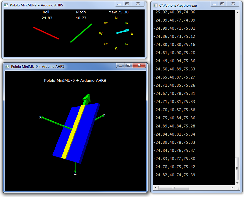
The nine independent rotation, acceleration, and magnetic readings provide all the data needed to make an attitude and heading reference system (AHRS), and readings from the absolute pressure sensor can be easily converted to altitudes, giving you a total of ten independent measurements (sometimes called 10DOF). With an appropriate algorithm, a microcontroller or computer can use the data to calculate the orientation and height of the AltIMU board. The gyro can be used to very accurately track rotation on a short timescale, while the accelerometer and compass can help compensate for gyro drift over time by providing an absolute frame of reference. The respective axes of the two chips are aligned on the board to facilitate these sensor fusion calculations. (For an example of such a system using an Arduino, see the picture below and the Sample Code section at the bottom of this page.)
 Side-by-side comparison of the MinIMU-9 v3 with the AltIMU-10 v4.
The carrier board includes a low-dropout linear voltage regulator that provides the 3.3 V required by the LPS25H, L3GD20H, and LSM303D, allowing the module to be powered from a single 2.5 V to 5.5 V supply. The regulator output is available on the VDD pin and can supply almost 150 mA to external devices. The breakout board also includes a circuit that shifts the I²C clock and data lines to the same logic voltage level as the supplied VIN, making it simple to interface the board with 5 V systems. The board’s 0.1" pin spacing makes it easy to use with standard solderless breadboards and 0.1" perfboards.
Specifications
- Dimensions: 1.0" x 0.5" x 0.1" (25 mm x 13 mm x 3 mm)
- Weight without header pins: 0.8 g (0.03 oz)
- Operating voltage: 2.5 V to 5.5 V
- Supply current: 6 mA
- Output format (I2C):
- Gyro: one 16-bit reading per axis
- Accelerometer: one 16-bit reading per axis
- Magnetometer: one 16-bit reading per axis
- Barometer: 24-bit pressure reading (4096 LSb/mbar)
- Sensitivity range:
- Gyro: ±245, ±500, or ±2000o/s
- Accelerometer: ±2, ±4, ±6, ±8, or ±16 g
- Magnetometer: ±2, ±4, ±8, or ±12 gauss
- Barometer: 260 mbar to 1260 mbar (26 kPa to 126 kPa)
Included Components
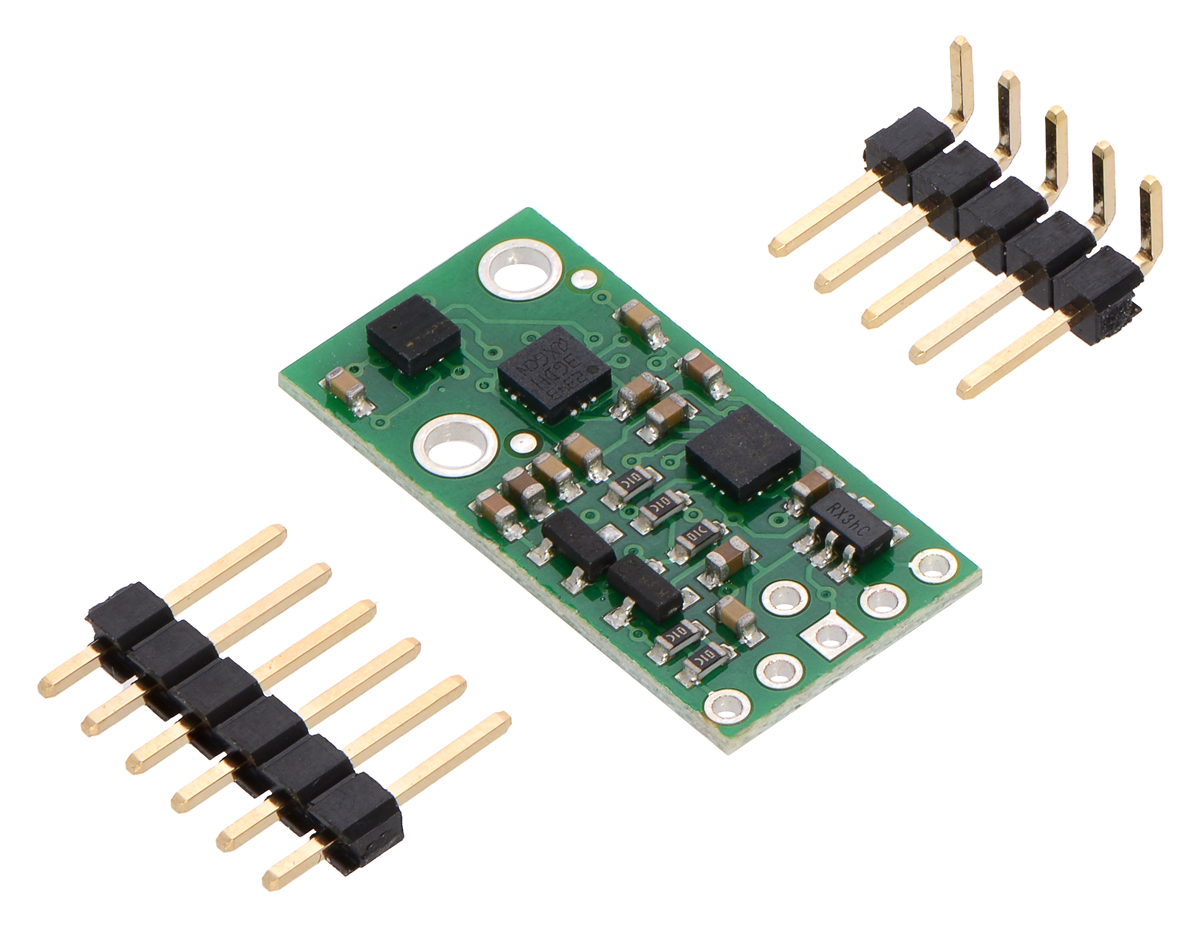
A 1x6 strip of 0.1" header pins and a 1x5 strip of 0.1" right-angle header pins are included, as shown in the picture below. You can solder the header strip of your choice to the board for use with custom cables or solderless breadboards or solder wires directly to the board itself for more compact installations. The board features two mounting holes that work with #2 or M2 screws (not included)
Using the AltIMU-10 v4
Connections
A minimum of four connections is necessary to use the AltIMU-10 v4: VIN, GND, SCL, and SDA. VIN should be connected to a 2.5 V to 5.5 V source, GND to 0 volts, and SCL and SDA should be connected to an I2C bus operating at the same logic level as VIN. (Alternatively, if you are using the board with a 3.3 V system, you can leave VIN disconnected and bypass the built-in regulator by connecting 3.3 V directly to VDD.)
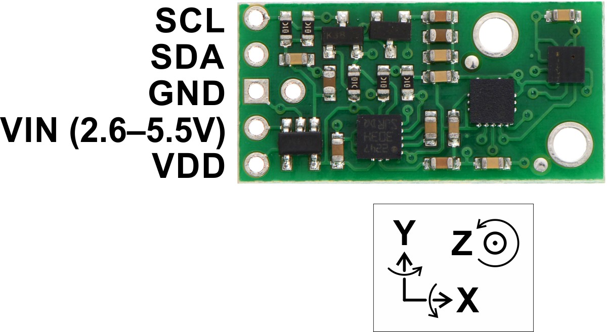 Pololu AltIMU-10 v4 gyro, accelerometer, compass, and altimeter pinout.
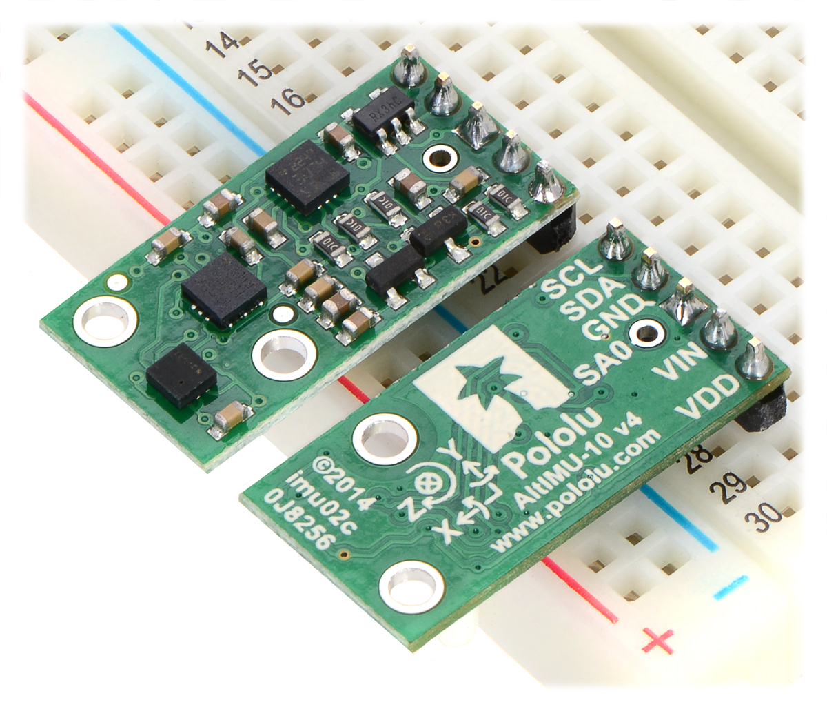 Two Pololu AltIMU-10 v4 modules in a breadboard.
Schematic Diagram
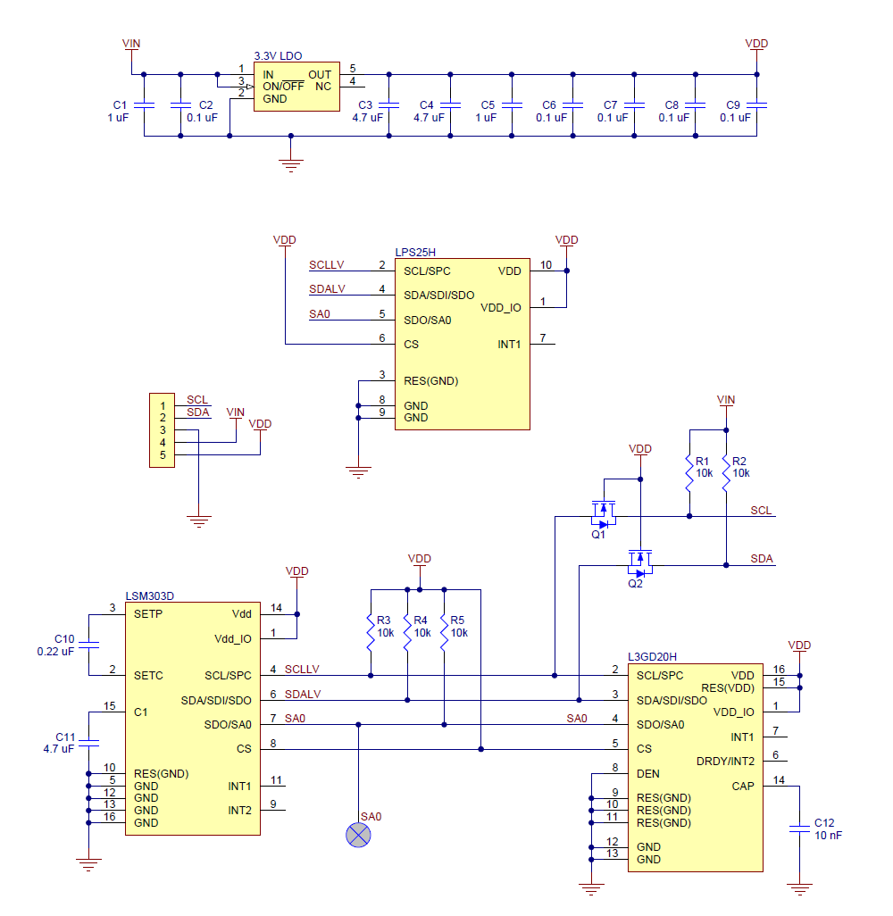
The above schematic shows the additional components the carrier board incorporates to make the LPS25H, L3GD20H, and LSM303D easier to use, including the voltage regulator that allows the board to be powered from a single 2.5 V to 5.5 V supply and the level-shifter circuit that allows for I2C communication at the same logic voltage level as VIN.
I2C Communication
The LPS25H’s barometer, the L3GD20H’s gyro, and the LSM303D’s accelerometer and magnetometer can be queried and configured through the I2C bus. Each of the four sensors acts as a slave device on the same I2C bus (i.e. their clock and data lines are tied together to ease communication). Additionally, level shifters on the I2C clock (SCL) and data lines (SDA) enable I2C communication with microcontrollers operating at the same voltage as VIN (2.5 V to 5.5 V). A detailed explanation of the protocols used by each device can be found in the LPS25H datasheet (1MB pdf), the L3GD20H datasheet (3MB pdf), and the LSM303D datasheet (1MB pdf). More detailed information about I2C in general can be found in NXP’s I2C-bus specification (1MB pdf).
The L3GD20H, LSM303D, and LPS25H each have separate slave addresses on the I2C bus. The board connects SA0 pins of the three ICs together and pulls them all to VDD through a 10 kΩ resistor. You can drive the SA0 pin low to change the slave address. This allows you to have two AltIMUs (or an AltIMU v4 and a MinIMU v3) connected on the same I2C bus.
Sample Code
We have written a basic LPS25H Arduino library, L3GD20 Arduino library, and LSM303 Arduino library that make it easy to interface the AltIMU-10 v4 with an Arduino or Arduino-compatible board like an A-Star. They also make it simple to configure the sensors and read the raw pressure, gyro, accelerometer, and magnetometer data.
For a demonstration of what you can do with this data, you can turn an Arduino connected to a AltIMU-10 v4 into an attitude and heading reference system, or AHRS, with this Arduino program. It uses the data from the AltIMU-10 v4 to calculate estimated roll, pitch, and yaw angles, and you can visualize the output of the AHRS with a 3D test program on your PC (as shown in a screenshot above). This software is based on the work of Jordi Munoz, William Premerlani, Jose Julio, and Doug Weibel.
Protocol Hints
- The datasheets provide all the information you need to use the sensors on the AltIMU-10 v4, but picking out the important details can take some time. Here are some pointers for communicating with and configuring the LPS25H, L3GD20H, and LSM303D that we hope will get you up and running a little bit faster:
- The pressure sensor, gyro, accelerometer, and magnetometer are all off by default. You have to turn them on by setting the correct configuration registers.
- You can read or write multiple pressure sensor, gyro, or accelerometer registers in a single I2C command by asserting the most significant bit of the register address to enable address auto-increment.
- Compared with previous LSM303-series sensors, the register interface to the magnetometer in the LSM303D is much more consistent with the accelerometer interface, and its accelerometer and magnetometer share a common I²C address instead of acting as two separate slave devices on the same bus.
- The pressure sensor has a 24-bit pressure reading. The gyro, accelerometer, and magnetometer all output readings in a 16-bit reading (obtained by combining the values in two 8-bit registers for each axis).
Don't delay. Buy today.
Add to cart now!
Reviews
Customers who bought this product also bought:
-
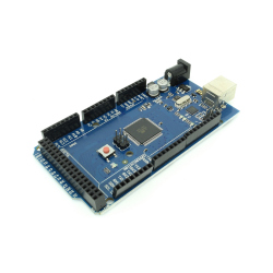
Development...
Development Board Compatible with Arduino MEGA...
92,37 lei
-
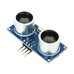
HC-SR04...
The HC-SR04 ultrasonic sensor is one of the...
6,49 lei