Dupa plasarea solicitării de comandă, in sectiunea Istoric puteti vedea cate solicitări de comandă mai avem de procesat inaintea dumneavoastra
Program de lucru: Luni - Vineri 8:30 - 17:30, pauza 12:30 - 13:30.
Se efectueaza lucrari de mentenanta la site si pot aparea erori. In cazul in care intampinati erori va rugam sa reincercati mai tarziu.
Ridicarea personala este disponibila pentru comenzile achitate in avans. Se pot ridica dupa ce sunt pregatite.
Niciun produs
") Mărește
Mărește
")
")
")
")
")
Senzor de Distanță Pololu 3-Channel Wide FOV cu OPT3101 (fără header de pini)
0104110000074713
Produs nou
Senzor de Distanță Pololu 3-Channel Wide FOV cu OPT3101 (fără header de pini)
Acest produs nu mai este in stoc
- Scrie o recenzie
- Elimina acest produs din lista mea de favorite.
- Adauga acest produs la lista mea de favorite.
- Imprimă
Recenzii
Clienții care au cumpărat acest produs au mai cumpărat:
-
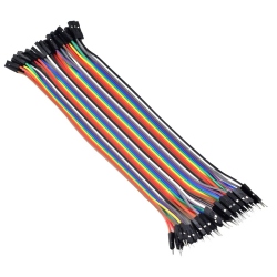
Fire...
Set Fire Mamă-Tată (40p, 30 cm)
$2.40
-
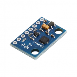
Modul...
Modul Accelerometru Digital MMA8452 potrivit...
$3.60
-
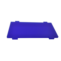
Placă pentru...
Această placă poate înlocui una deteriorată sau...
$0.72
-
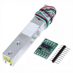
Celula de...
Celula de Sarcina de 10 kg cu Amplificator HX711
$6.72
-
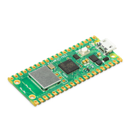
Raspberry Pi...
Produs Original
$8.28
-
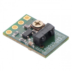
Senzor de...
Senzor de proximitate Pololu ce poate detecta...
$7.20
-
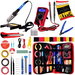
Kit Plusivo...
Kit complet de lipit: Include toate uneltele...
$24.00
-

Celula de...
Celula de Sarcina de 5 kg cu Amplificator HX711
$6.20
-
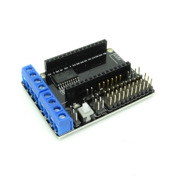
Driver de...
Modul driver de motoare L293DD la care puteți...
$4.80
-

Senzor de...
Acest senzor este un mini radar ce se bazează...
$1.80