Dupa plasarea solicitării de comandă, in sectiunea Istoric puteti vedea cate solicitări de comandă mai avem de procesat inaintea dumneavoastra
Program de lucru: Luni - Vineri 8:30 - 17:30, pauza 12:30 - 13:30.
Se efectueaza lucrari de mentenanta la site si pot aparea erori. In cazul in care intampinati erori va rugam sa reincercati mai tarziu.
Ridicarea personala este disponibila pentru comenzile achitate in avans. Se pot ridica dupa ce sunt pregatite.
Niciun produs
 Mărește


Sursă Coborâtoare de Tensiune de 5V, 9A Pololu D24V90F5
0104110000044983
Produs nou
Sursă Coborâtoare de Tensiune de 5V, 9A Pololu D24V90F5 utilă pentru proiectele ce au nevoie de o tensiune de 5V, la un curent mare, de până la 9A.
Produsele care pot aparea in imagini precum breadboard, fire, surse etc, sunt utilizate cu titlu de sugestie de prezentare.
Acest produs nu mai este in stoc
- Scrie o recenzie
- Elimina acest produs din lista mea de favorite.
- Adauga acest produs la lista mea de favorite.
- Imprimă
Informații
Caracteristici tehnice:
- Tensiune de intrare: 5V - 38V;
- Tensiune de ieșire: 5V (poate fi micșorată cu ajutorul unei rezistențe de feedback);
- Acuratețe tensiune de ieșire: 4%;
- Curent maxim de ieșire: 9A (în funcție de disiparea de căldură asigurată);
- Curent maxim de scurgere în gol: 15mA (tipic 180uA);
- Curent maxim de scurgere în gol (mod shutdown): 20uA / Volt;
- Eficiență tipică: 80% - 95%, în funcție de punctul de funcționare;
- Protecție la alimentare inversă, supracurent, supratemperatură (160°C) și subtensiune;
- Soft-start;
- Pin power good ce indică funcționarea normală a sursei;
- Dimensiuni: 40.6 x 20.3 x 7.6 mm.
Acest produs reprezintă o sursă coborâtoare de tensiune, ce funcționează în comutație, și oferă un randament de până la 95%, astfel că foarte puțină energie este pierdută. Sursa este utilă pentru circuite ce consumă un curent mare, de până la 9A.
Sursa are dimensiuni mici și are o gamă largă de protecții, astfel că poate fi inclusă cu ușurință într-o gamă largă de proiecte.
Pentru mai multe detalii, consultați pagina producătorului.
Recenzii
Clienții care au cumpărat acest produs au mai cumpărat:
-
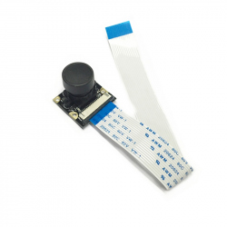
Cameră...
Cameră pentru Raspberry Pi cu unghi de...
$36.00
-
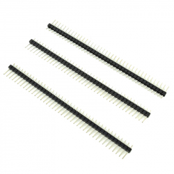
Header de...
40 de pini care pot fi taiati la dimensiunea...
$0.24
-
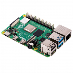
Raspberry Pi...
Produs Original Cea mai nouă serie de plăci...
$72.58
-
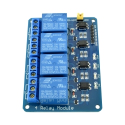
Modul cu 4...
Modulul cu 4 relee este util pentru controlul a...
$3.33
-
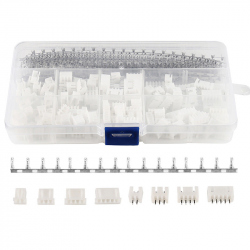
Kit...
Kit Conectori XH2.54 (560 buc)
$8.40
-
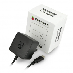
Alimentator...
Produs Original Alimentator de 3 A, 5 V,...
$10.56
-
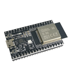
Placa de...
Această placă de dezvoltare are la bază...
$16.80
-
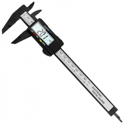
Șubler...
Șubler Digital Negru Bateria nu este inclusa!
$7.20
-
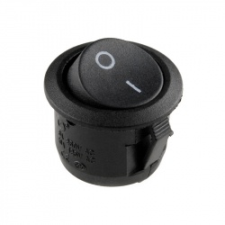
Intrerupator...
Intrerupator Rotund
$0.29
-
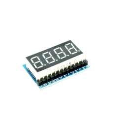
Modul...
Modul Display LED cu 4 Cifre, fiecare a câte 7...
$1.92