Dupa plasarea solicitării de comandă, in sectiunea Istoric puteti vedea cate solicitări de comandă mai avem de procesat inaintea dumneavoastra
Program de lucru: Luni - Vineri 8:30 - 17:30, pauza 12:30 - 13:30.
Se efectueaza lucrari de mentenanta la site si pot aparea erori. In cazul in care intampinati erori va rugam sa reincercati mai tarziu.
Ridicarea personala este disponibila pentru comenzile achitate in avans. Se pot ridica dupa ce sunt pregatite.

No products
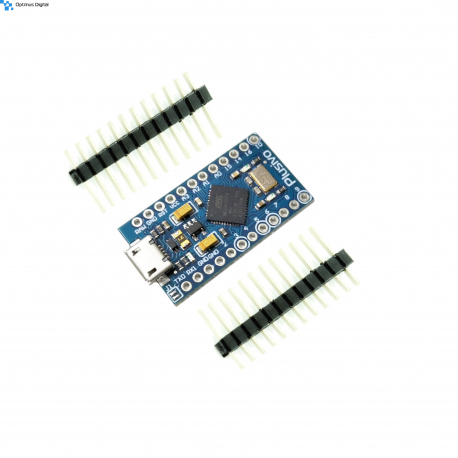 View larger
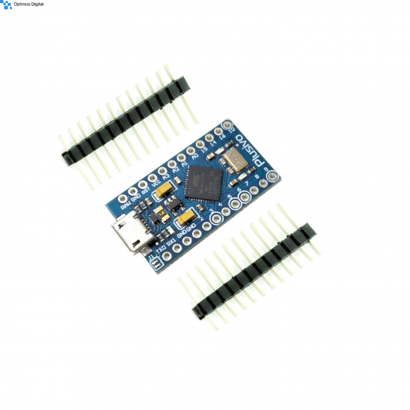


Development Board Compatible with Arduino Pro Micro
0104110000000354
New product
This development board is the best choice for electronic projects that require a small space occupied by the microcontroller. This board also features a micro-USB connector.
See description for more details about the product.
Add to cart now!
190 Items
- Write a review
- Remove this product from my favorite's list.
- Add this product to my list of favorites.
Accessories
Must-have Accessories
More info
Description
This development board is the best choice for electronic projects that require a small space occupied by the microcontroller.
Specifications
- Operating voltage: 5 V
- Pin I / O: 12
- PWM pin: 5 (of the I / O)
- ADC pin 4 (of the I / O)
- SPI and UART communication
- Flash Memory: 32KB (8 busy bootloader)
- Operating frequency: 16 MHz
- Arduino Compatible with v1.0.1
- Dimensions: 3.3 x 1.77 cm
Instructions for use
1. Install the Arduino IDE development environment.
Arduino IDE is available for free on the official website and can be downloaded by accessing this link. This program is compatible with most development systems (Linux, Mac OS X and Windows).
2. Configure the development environment for use with the development board.
Open the "INSTRUMENTS" tab and select the "Arduino/Genuino Micro" development board.
3. Creating the code.
After you install Arduino IDE, you can write the first program for the development board. The programming language used is C ++ (slightly modified).
The code is based on two main functions:
- "Void setup ()" function: This runs only once when the development board is started. Usually, this function is used to initialize pins (such as INPUT or OUTPUT) or to start serial communication ("Serial.begin");
- "Void loop ()" function: This runs endlessly until the board is switched off. This feature is usually useful for reading measured data from various sensors attached to the development board or for updating data on an LCD screen.
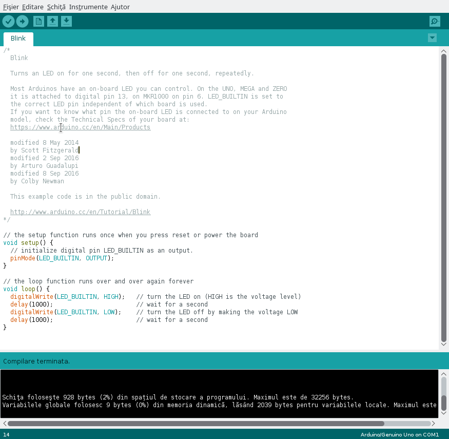
After you have written the program or opened one of the File -> Examples, press the "Check" button or the CTRL + R shortcut to compile the code. If the code is free of syntax errors, the text "Compilation completed" should appear at the bottom. In the case of a contract, an error message will appear that should help correct the error.
In the image attached below you can see an example of a "Blink" code that was successfully compiled.
4. Connect the development board and upload the code.
Connect the board to the computer via a USB cable. After you have connected the board, open the "INSTRUMENTS" tab and select the port to which the device is connected.
Press the "Upload" button or CTRL + U shortcut to upload the code to the development board. After you finish writing the code in the memory of the board, you will receive a confirmation message that there were no problems. Otherwise, the upload is stopped and details about the issues will be displayed.
5. Attach the sensors.
The board is compatible with the Arduino Pro Micro, so any sensor for the Arduino Pro Micro can be used with this product.
CAREFUL!!! Be careful not to connect components that consume too much power because you risk breaking the board. Also, observe the polarity of the sensors so as not to destroy them.
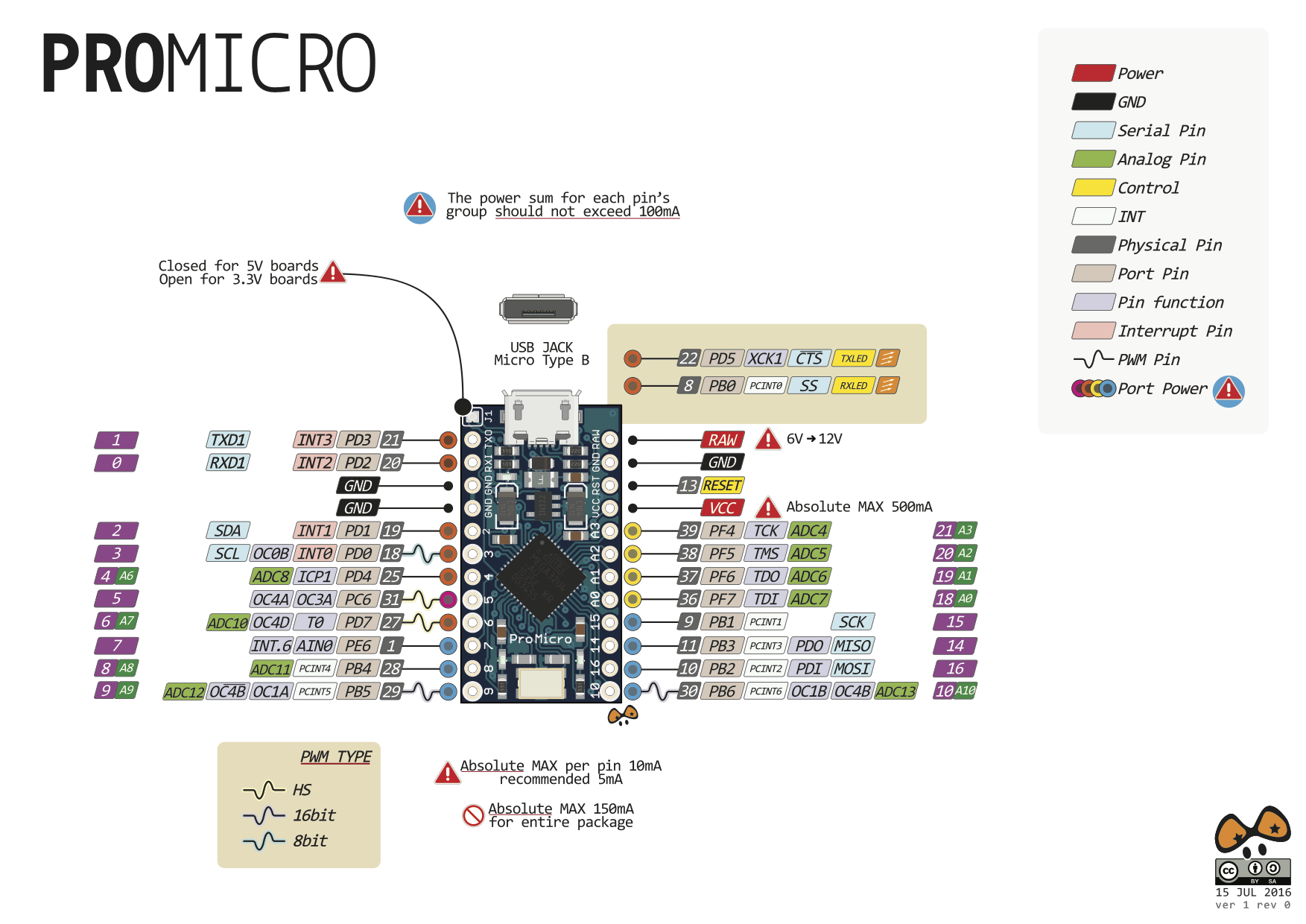
In the image attached below you can see the map of the pines. This is useful when you need to use special pins, such as PWM, ADC, SDA, SCL, etc.
Don't delay, buy today.
Add to cart now!
Reviews
Customers who bought this product also bought:
-
M6x25 mm...
M6x25 mm Hexagonal Head Screw See description...
$0.29
-
5 V, 2.5 A...
5 V, 2.5 A Power Adapter for Raspberry Pi 3 and...
$7.20
-
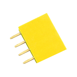
4p 2.54 mm...
4p 2.54 mm Female Pin Header (Yellow) See...
$0.12
-
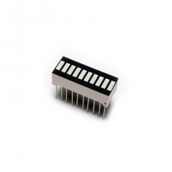
Red LED Bar...
Red LED bar with 10 useful display segments for...
$0.47
-
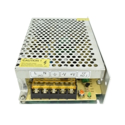
5 V 10 A (50...
Source 5 V switching regulator 10 A (50 W)....
$11.52
-
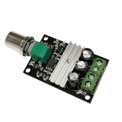
PWM Motor...
PWM Motor Speed Controller See description for...
$6.00
-
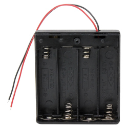
Battery Case...
This battery case with cover can hold 4 x R6...
$1.52
-
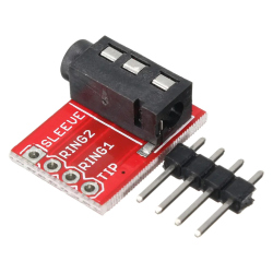
3.5 mm...
3.5 mm Stereo Audio Jack Module See...
$0.47
-
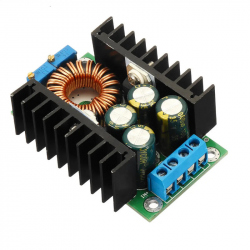
12 A...
12 A adjustable step-down voltage source which...
$6.72
-
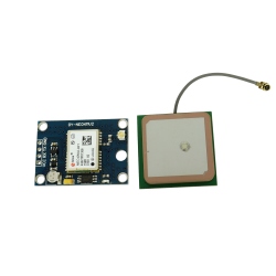
GY-NEO6MV2...
This features the u-blox NEO-6M GPS module with...
$10.79