Dupa plasarea solicitării de comandă, in sectiunea Istoric puteti vedea cate solicitări de comandă mai avem de procesat inaintea dumneavoastra
Program de lucru: Luni - Vineri 8:30 - 17:30, pauza 12:30 - 13:30.
Se efectueaza lucrari de mentenanta la site si pot aparea erori. In cazul in care intampinati erori va rugam sa reincercati mai tarziu.
Ridicarea personala este disponibila pentru comenzile achitate in avans. Se pot ridica dupa ce sunt pregatite.

 Mărește


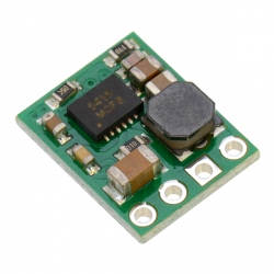
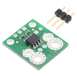
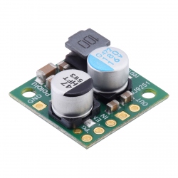
Sursă de Tensiune Ridicătoare/Coborâtoare Reglabilă 9V - 30V Pololu S18V20AHV
0104110000035974
Produs nou
Sursă de Tensiune Ridicătoare/Coborâtoare Reglabilă 9V - 30V Pololu S18V20AHV utilă pentru proiecte în care tensiunea de intrare poate varia sub sau peste tensiunea de ieșire.
Alte produse care pot aparea in imagini sunt folosite drept sugestie de prezentare.
Acest produs nu mai este in stoc
- Scrie o recenzie
- Elimina acest produs din lista mea de favorite.
- Adauga acest produs la lista mea de favorite.
- Imprimă
Informații
Caracteristici tehnice:
- Tensiune de intrare: 2.9V - 32V (maxim recomandat 30V);
- Tensiune de ieșire reglabilă: 9V - 30V;
- Curent maxim de ieșire: 2A (în funcție de tensiunea de intrare și cea de ieșire);
- Protecție la alimentare inversă (până la 30V), supracurent, supratemperatură și subtensiune;
- Eficiență tipică între 80% și 90%, în funcție de punctul de funcționare;
- Curent maxim de scurgere în gol: 25mA;
- Curent maxim de scurgere în gol în mod shut-down: 20uA/Volt;
- Masă: 7.5 grame;
- Dimensiuni: 43 x 21 x 10 mm.
Acest produs reprezintă o sursă de tensiune în comutație de tip buck-boost, concepută în topologie SEPIC. Ea este utilă în proiectele dumneavoastră în care aveți nevoie de o tensiune de ieșire fixă, indiferent de valoarea tensiunii de intrare, fie ea mai mică sau mai mare.
Sursă are dimensiuni mici și funcționează în comutație, astfel că poate fi inclusă cu ușurință într-o gamă largă de proiecte. Ea are randament bun si disipă foarte puțină căldura.
Pentru mai multe informații, consultați pagina producătorului.
Recenzii
Clienții care au cumpărat acest produs au mai cumpărat:
-

Modul DC-DC...
Modul DC - DC step down proiectat pentru a...
$1.25
-
Modul cu...
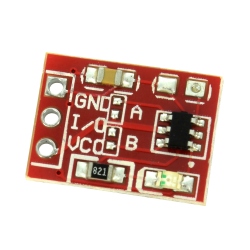
Modul cu senzor capacitiv TTP223 potrivit...
$0.71
-
Sursă Pololu...
Sursă Pololu Step-Down D24V5F3 ce poate fi...
$11.52
-
Mini...
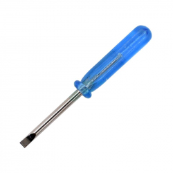
Mini Șurubelniță Dreaptă Albastră de 2 mm
$0.36
-
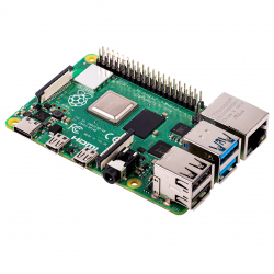
Raspberry Pi...
Produs Original În cea mai nouă serie de...
$98.97
-
Senzor de...
Acest transportator este echipat cu...
$20.16
-
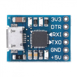
Modul...
Modul convertor Micro USB la Serial CP2102...
$3.60
-
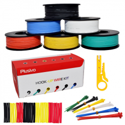
Set de fire...
Kit de Cabluri 24AWG Multifilare: Kitul include...
$12.00
-
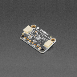
Modul Senzor...
Acest modul poate măsura temperatura,...
$36.24
-
Sursă...
Sursă Step-Down Pololu D24V22F12 de 12 V, 2.2 A...
$58.80