Dupa plasarea solicitării de comandă, in sectiunea Istoric puteti vedea cate solicitări de comandă mai avem de procesat inaintea dumneavoastra
Program de lucru: Luni - Vineri 8:30 - 17:30, pauza 12:30 - 13:30.
Se efectueaza lucrari de mentenanta la site si pot aparea erori. In cazul in care intampinati erori va rugam sa reincercati mai tarziu.
Ridicarea personala este disponibila pentru comenzile achitate in avans. Se pot ridica dupa ce sunt pregatite.

Niciun produs
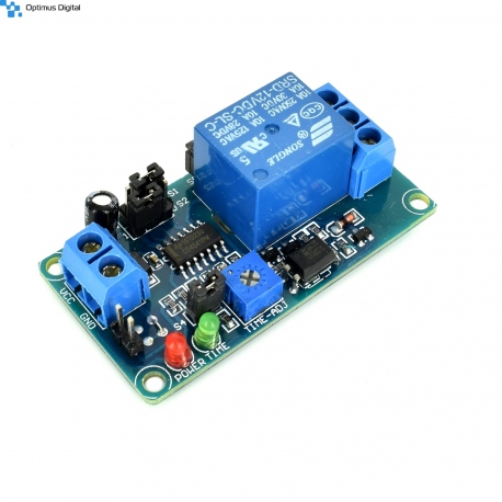 Mărește
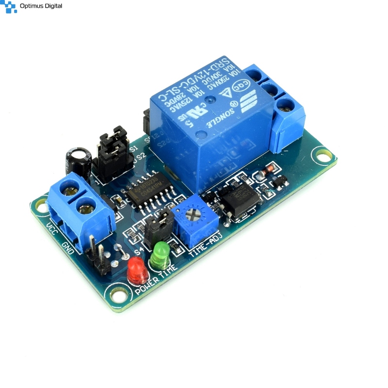
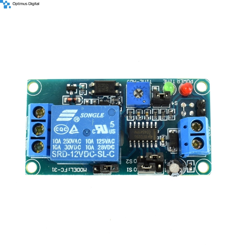
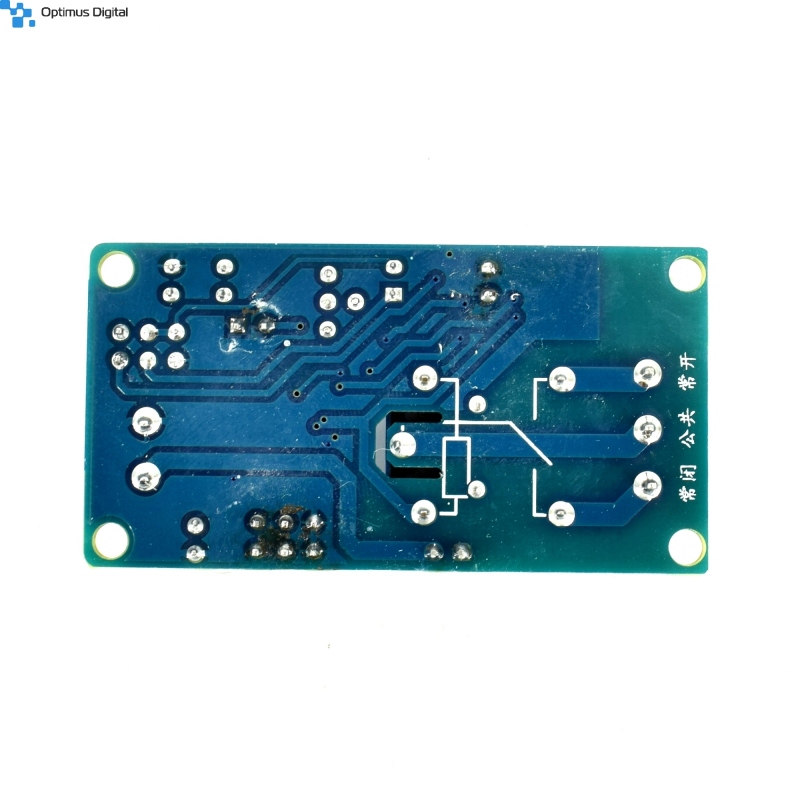
Modul Releu Normal Deschis cu Întârziere
0104110000023674
Produs nou
Modul Releu Normal Deschis cu Întârziere
385 bucati in stoc
- Scrie o recenzie
- Elimina acest produs din lista mea de favorite.
- Adauga acest produs la lista mea de favorite.
- Imprimă
Informații
Caracteristici tehnice:
- Tensiunea de alimentare: 12 V DC;
- Tensiunea maximă suportată: 250 V AC sau 30 V DC;
- Curent maxim suportat: 10 A;
- Dimensiuni: 5.5 cm x 2.9 cm x 1.8 cm;
Instrucțiuni de utilizare:
1. Alimentarea modulului.
Modulul se alimentează cu o tensiune de 12 V DC. Terminalele cu șuruburi sunt marcate cu VCC și GND.
ATENȚIE!!!Aveți grijă să respectați polaritatea astfel riscați să stricați produsul.
2. Cuplarea releului.
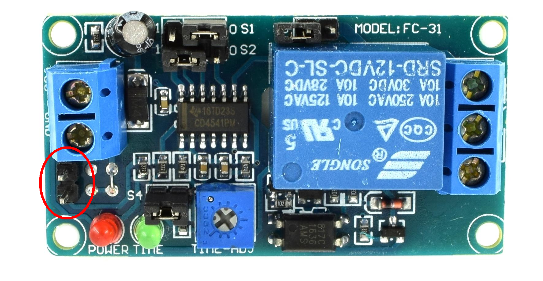
Releul este cuplat atunci când se realizează conexiunea între pinii încercuiți cu roșu în poza atașată mai jos și rămâne activat o durată de timp configurabilă cu ajutorul jumperelor S1, S2 și S4 și prin intermediul potențiometrului albastru marcat cu TIME-ADJ. Led-ul verde aprins pe toată durata activării releului.
3. Configurarea timpului de cuplare.
Consultați tabelul atașat mai jos pentru a configura timpul de cuplare a releului. De asemenea, releul este cuplat atunci când led-ul verde este aprins.
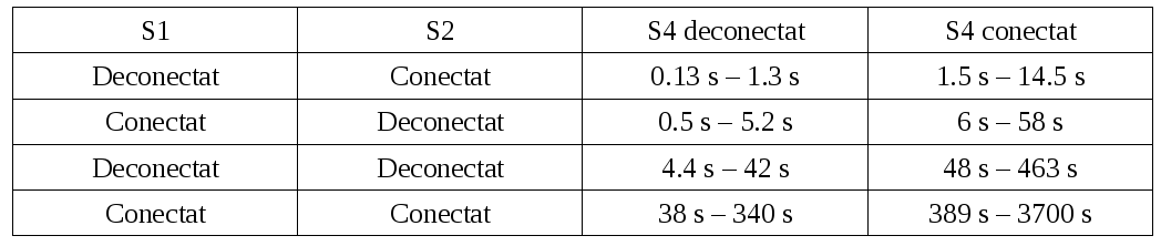
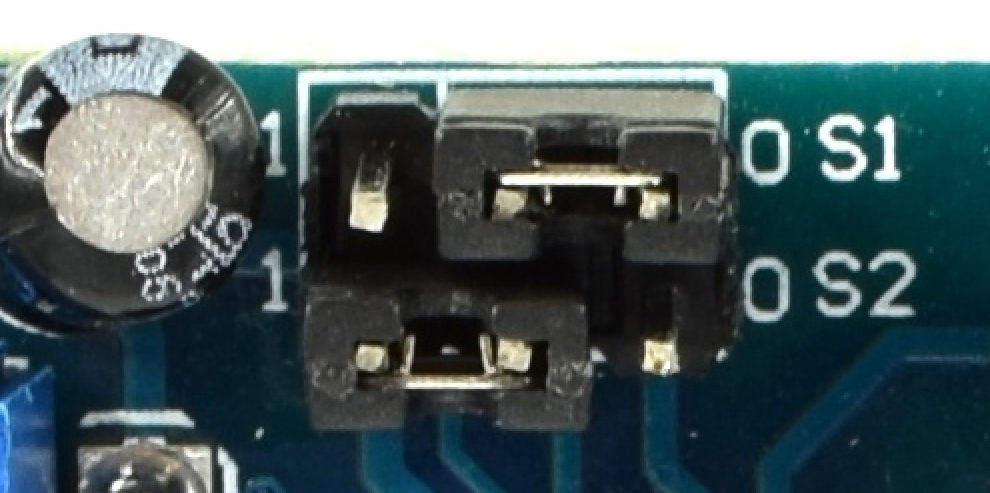
Exemplu: În imaginea atașată mai jos, jumperul S1 este deconectat, iar jumperul S2 este conectat. Astfel, timpul de cuplare este cuprins între 0.13 secunde și 1.3 secunde. În continuare, timpul se ajustează cu potențiometrul albastru. Timpul scade atunci când este rotit în sensul invers acelor de ceasornic și crește atunci când este rotit în sensul acelor de ceasornic.
Recenzii
Clienții care au cumpărat acest produs au mai cumpărat:
-
Cântar...
Cu acest cântar puteți efectua măsurători de...
$4.80
-
Sursă de...
Sursă de tensiune coborâtoare reglabilă de 12 A...
$6.72
-
Modul Releu...
Modul Releu M118 (5 V)
$1.92
-
Motor Pas cu...
Motor Pas cu Pas Plusivo 23HS5628
$21.60
-
Carcasă...
Carcasă pentru Baterie Portabilă Neagră
$2.40
-
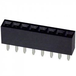
Header de...
Header de Pini Mamă 8p 2.54 mm
$0.12
-
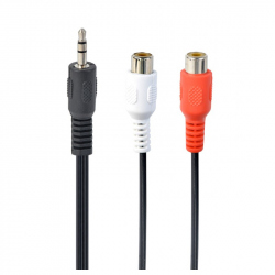
Cablu Audio...
Cablu Audio Adaptor de la Jack de 3.5 mm la 2 x...
$0.60
-
Header de...
Header de pini galben 2.54 mm (40p)
$0.24
-
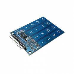
Modul Senzor...
Modul Senzor de Atingere Capacitiv TTP229 este...
$2.08
-
Modul...
Acest modul MPU6500 integrează giroscop cu 3...
$4.80