Dupa plasarea solicitării de comandă, in sectiunea Istoric puteti vedea cate solicitări de comandă mai avem de procesat inaintea dumneavoastra
Program de lucru: Luni - Vineri 8:30 - 17:30, pauza 12:30 - 13:30.
Se efectueaza lucrari de mentenanta la site si pot aparea erori. In cazul in care intampinati erori va rugam sa reincercati mai tarziu.
Ridicarea personala este disponibila pentru comenzile achitate in avans. Se pot ridica dupa ce sunt pregatite.

No products
 View larger
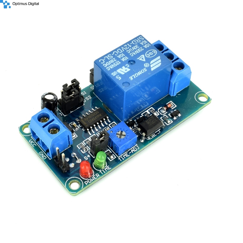
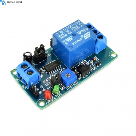
12 V Relay with Adjustable Delay
0104110000023674
New product
Regular normal relay mode with delay.
See description for more details about the product.
Add to cart now!
385 Items
- Write a review
- Remove this product from my favorite's list.
- Add this product to my list of favorites.
More info
Technical specifications
- Supply voltage: 12 V DC
- Supported maximum voltage: 250 V AC or 30 V DC
- Maximum supported current: 10 A
- Dimensions: 5.5 cm x 2.9 cm x 1.8 cm
Instructions for use
1. Power the module.
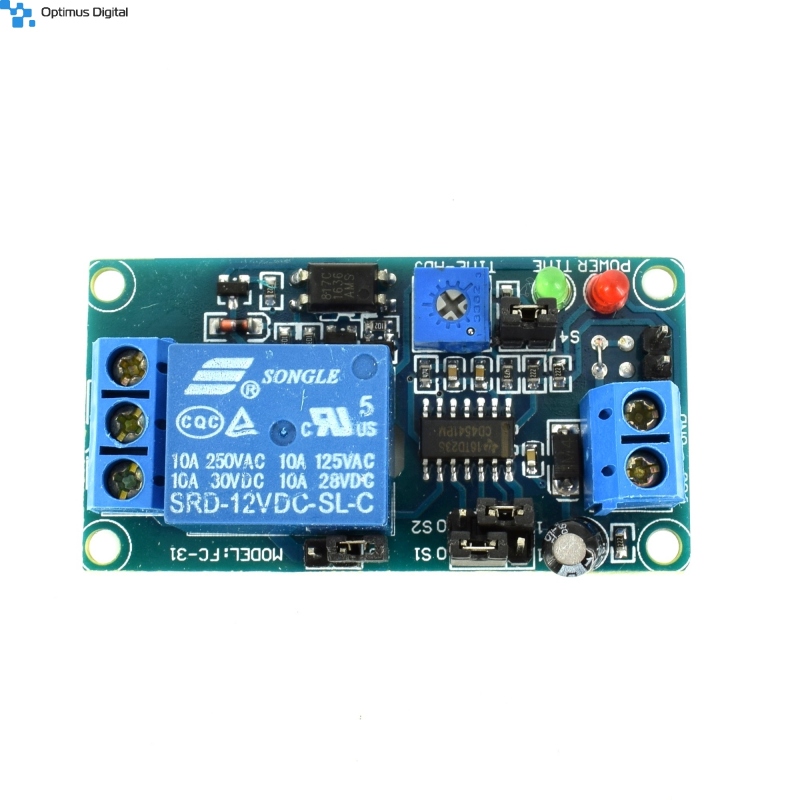
The module is powered by a 12 V DC voltage. Screw terminals are marked with VCC andGND.
WARNING! Be careful to observe the polarity, thus damaging the product.
2. Relay coupling.
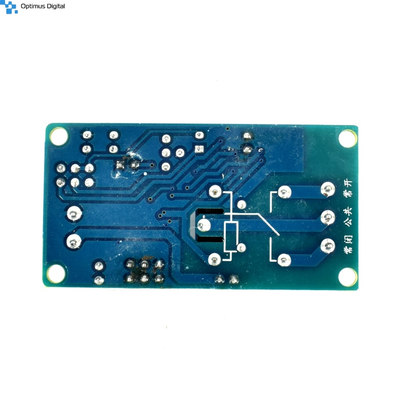
The relay is coupled when the connection between the red-pinned pins is attached to the picture attached below and a configurable time is activated with the S1, S2 and S4 jumper and via the blue potentiometer marked TIME-ADJ. The green LED illuminates during the relay activation.
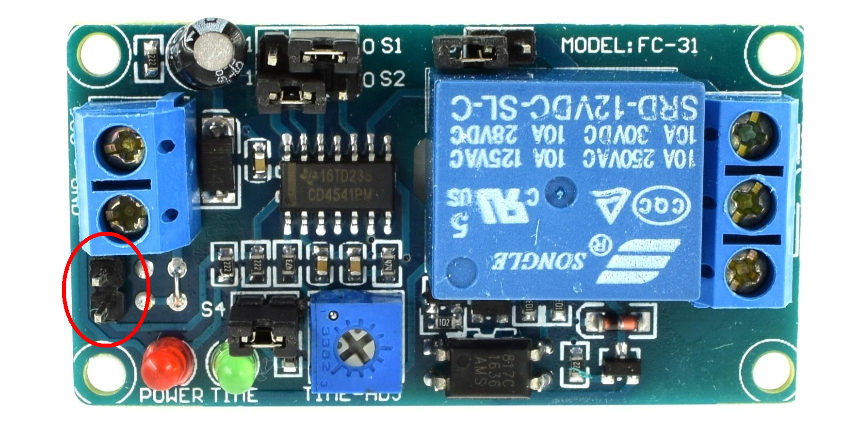
3. Setting the coupling time.
Refer to the attached table below to configure the relay switching time. Also, the relay is switched on when the green LED is on.
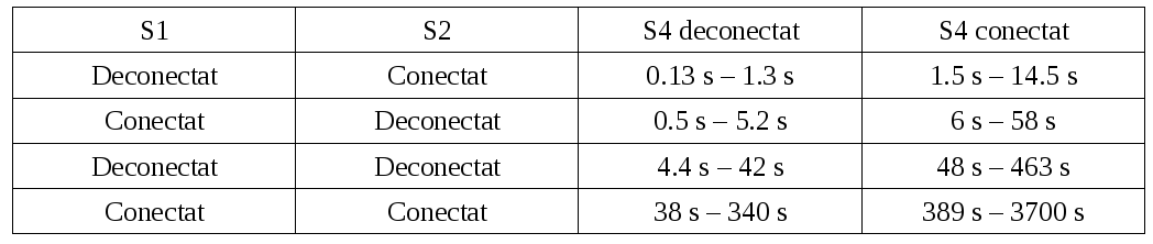
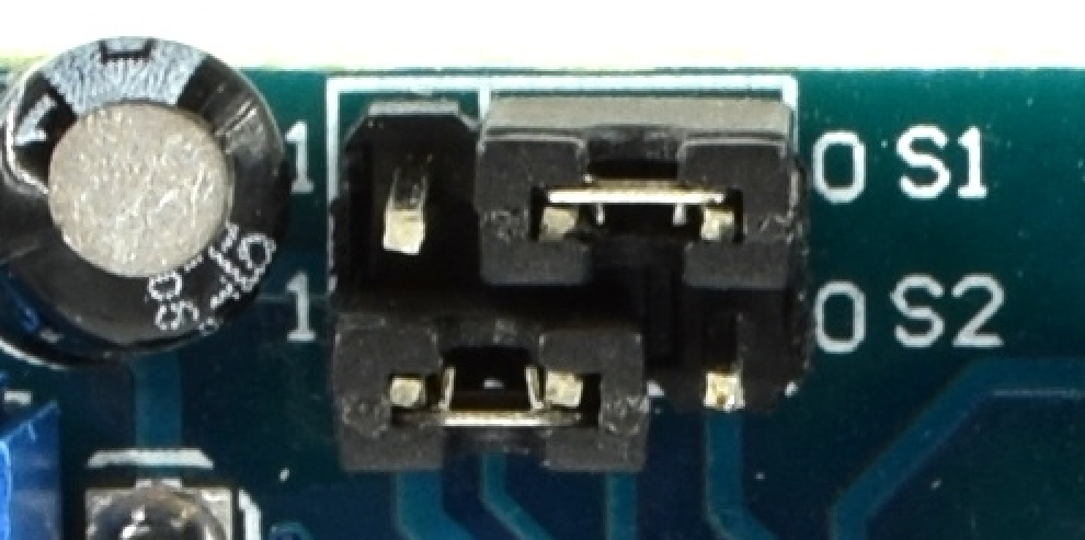
Example: In the attached picture below, jumper S1 is disconnected and jumper S2 is connected. Thus, the coupling time is between 0.13 seconds and 1.3 seconds. Then the time is adjusted with the blue potentiometer. The time decreases when it is rotated counterclockwise and increases when it is rotated clockwise.
Don't delay, buy today.
Add to cart now!
Reviews
Customers who bought this product also bought:
-
3.7V to 12V...
Input Voltage:2.5V~VOUT-0.5V Output Voltage:...
4,99 lei
-
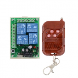
DC12V 4CH...
This module has the advantage of being remote...
62,99 lei
-
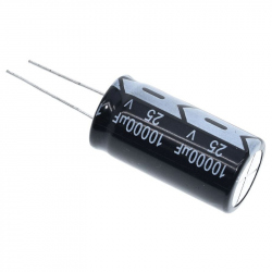
Electrolytic...
An Electrolytic Capacitor that has a...
6,99 lei
-
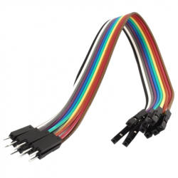
10 cm 10p...
Ideal wires for making connections for...
2,99 lei
-
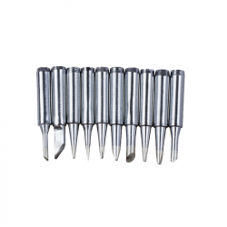
Soldering...
Soldering Iron Tip Set (10 pcs)
22,99 lei
-
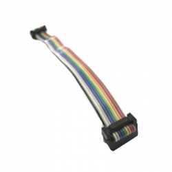
Cable for...
Cable for UIC00B PIC Programmer See...
9,99 lei
-
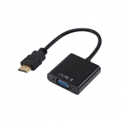
HD-VGA...
HD-VGA Convertor (Black) See description for...
29,99 lei
-

0-30 V Red...
This is a 0-30 V red panel voltmeter showing...
9,99 lei
-
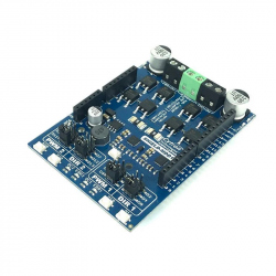
10Amp 7V-30V...
Building a mobile robot with Arduino? Want to...
129,00 lei
-
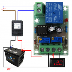
M601...
M601 Charging Controller Module for 12 V...
19,99 lei