Dupa plasarea solicitării de comandă, in sectiunea Istoric puteti vedea cate solicitări de comandă mai avem de procesat inaintea dumneavoastra
Program de lucru: Luni - Vineri 8:30 - 17:30, pauza 12:30 - 13:30.
Se efectueaza lucrari de mentenanta la site si pot aparea erori. In cazul in care intampinati erori va rugam sa reincercati mai tarziu.
Ridicarea personala este disponibila pentru comenzile achitate in avans. Se pot ridica dupa ce sunt pregatite.
No products
 View larger


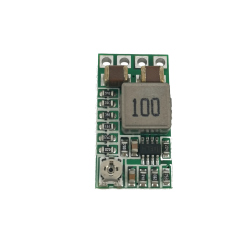
4-25V Adjustable Step-down Voltage Regulator D36V6AHV
0104110000068651
New product
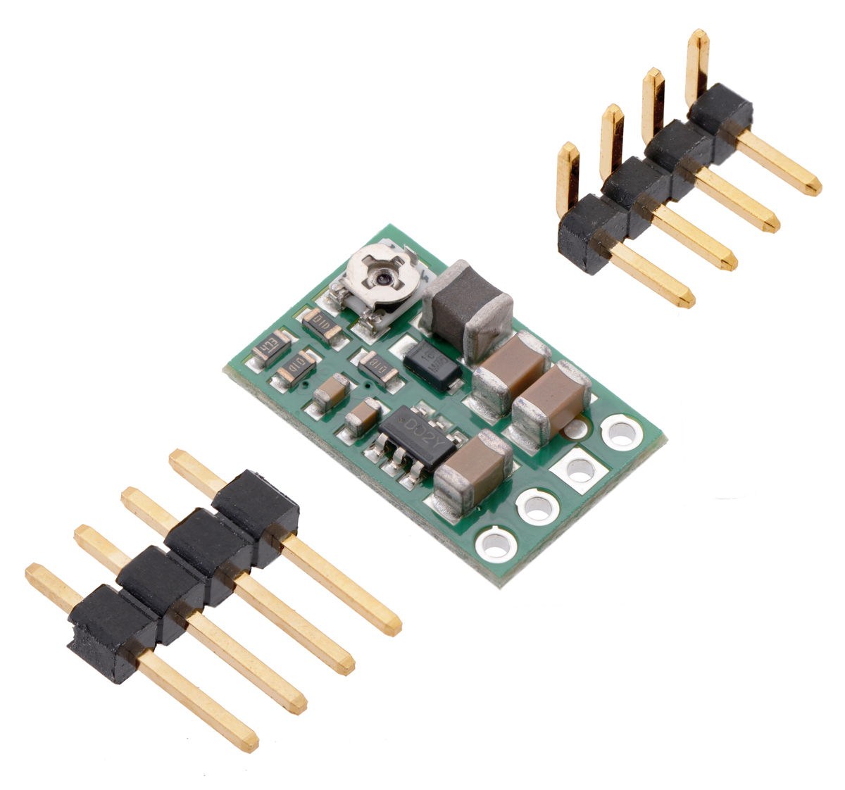
This compact (0.4" x 0.5") switching step-down (or buck) voltage regulator takes input voltages between 4 V and 50 V and efficiently reduces them to a lower, user-adjustable voltage set by an on-board trimmer potentiometer. It has an output voltage range of 4 V to 25 V and a maximum output current of 600 mA. It has a very low dropout, so it can be used with input voltages that are within a few hundred millivolts of its output. The pins have a 0.1" spacing, making this board compatible with standard solderless breadboards and perfboards.
NO Reverse voltage protection!
See description for more details about the product.
Add to cart now!
This product is no longer in stock
- Write a review
- Remove this product from my favorite's list.
- Add this product to my list of favorites.
More info
Overview
The D36V6x family of buck (step-down) voltage regulators generates lower output voltages from input voltages as high as 50 V. They are switching regulators (also called switched-mode power supplies (SMPS) or DC-to-DC converters), which makes them much more efficient than linear voltage regulators, especially when the difference between the input and output voltage is large. This family includes seven versions with fixed output voltages ranging from 3.3 V to 15 V and two adjustable versions that can be set using a trimmer potentiometer:
• D36V6F3: Fixed 3.3V output
• D36V6F5: Fixed 5V output
The regulators feature short-circuit/over-current protection, and thermal shutdown helps prevent damage from overheating. The boards do not have reverse-voltage protection.
Features
• Input voltage: 4 V to 50 V (input must exceed the output by the dropout voltage)
• Output voltage: adjustable from 4 V to 25 V by on-board trimmer potentiometer
• Maximum output current: 600 mA
• Fixed 2.1 MHz switching frequency
• High-voltage enable input can put the board into a low-power state where it draws less than 2 μA (typical)
• Low quiescent current: < 2 mA
• Over-current and short-circuit protection, over-temperature shutoff
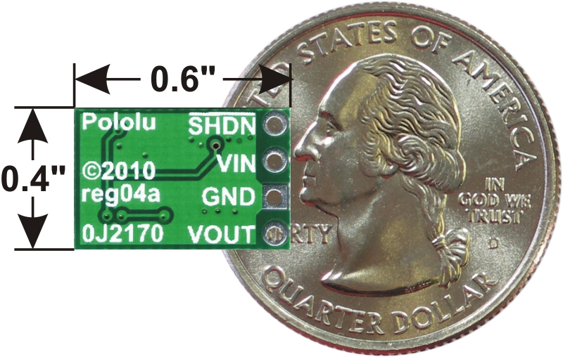
• Small size: 0.6" x 0.4" x 0.15" (15 mm x 10 mm x 4 mm)
• Weight: 0.6 g
Connections
This regulator has four connections: shutdown (SHDN), input voltage (VIN), ground (GND), and output voltage (VOUT).
The SHDN pin can be driven low (under 1.25 V) to turn off the output and put the board into a low-power state (< 2 μA typical). The regulator is enabled by default, and this input can be left disconnected if you do not need this feature.
The input voltage, VIN, powers the regulator and should be between 4 V and 50 V. If the input voltage gets too close to the output voltage, the output will start to drop, so you should ensure that VIN exceeds VOUT by at least the dropout voltage, which varies with the output voltage and the load. Additionally, please be wary of destructive LC spikes.
The output voltage, VOUT, is determined by the trimmer potentiometer position, with clockwise turns increasing the output voltage. You can use a multimeter to measure the output as you set it. Please note that the output voltage can be affected by a screwdriver touching the potentiometer, so the output measurement should be done with nothing touching the potentiometer. When setting the output voltage, note that the buck regulator can only produce voltages lower than the input voltage. The following graph shows approximately how the potentiometer position maps to the output voltage settings on the D36V6ALV (blue curve) and D36V6AHV (red curve).

Output voltage settings for the adjustable 2.5-7.5V and 4-25V buck regulators (D36V6Ax/D24V6Ax/D24V3Ax).
The four connections are labeled on the back side of the PCB and are arranged with a 0.1" spacing along the edge of the board for compatibility with solderless breadboards, connectors, and other prototyping arrangements that use a 0.1" grid. You can solder wires directly to the board or solder in either the 4x1 straight male header strip or the 4x1 right-angle male header strip.
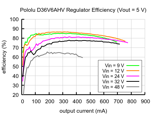
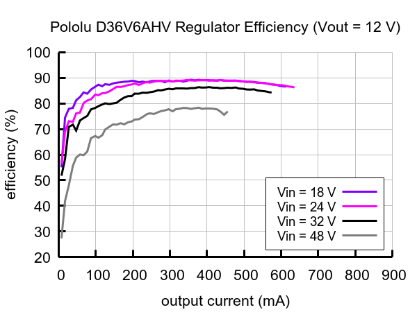
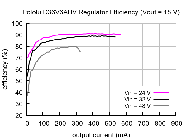
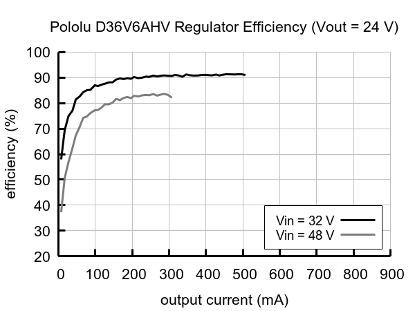
Typical efficiency
The efficiency of a voltage regulator, defined as (Power out)/(Power in), is an important measure of its performance, especially when battery life or heat are concerns.
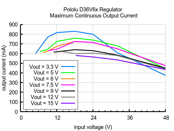
Maximum continuous output current
The maximum achievable output current of these regulators varies with the input voltage but also depends on other factors, including the ambient temperature, air flow, and heat sinking. The graph below shows maximum output currents that these regulators can deliver continuously at room temperature in still air and without additional heat sinking.
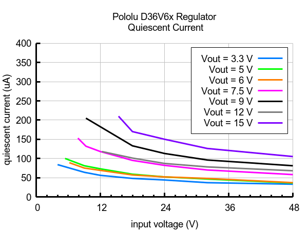
Quiescent current
The quiescent current is the current the regulator uses just to power itself, and the graph below shows this for the different regulator versions as a function of the input voltage. The module’s SHDN input can be driven low to put the board into a low-power state where it typically draws under 2 μA.
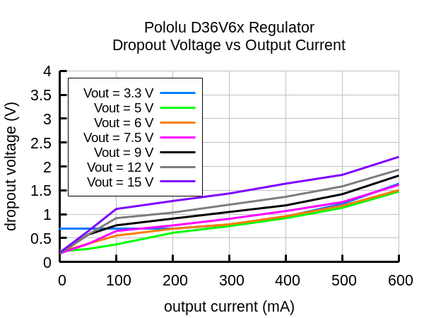
Typical dropout voltage
The dropout voltage of a step-down regulator is the minimum amount by which the input voltage must exceed the regulator’s target output voltage in order to ensure the target output can be achieved. For example, if a 5 V regulator has a 1 V dropout voltage, the input must be at least 6 V to ensure the output is the full 5 V. Generally speaking, the dropout voltage increases as the output current increases. The graph below shows the dropout voltages for the different members of this regulator family:
LC voltage spikes
When connecting voltage to electronic circuits, the initial rush of current can cause voltage spikes that are much higher than the input voltage. If these spikes exceed the regulator’s maximum voltage (50 V), the regulator can be destroyed. In our tests with typical power leads (~30" test clips), input voltages above 28 V caused spikes over 50 V.
If you are connecting more than 28 V or your power leads or supply has high inductance, we recommend soldering a suitably rated 33 μF or larger electrolytic capacitor close to the regulator between VIN and GND.
More information about LC spikes can be found in our application note, Understanding Destructive LC Voltage Spikes.
Specifications
Dimensions
| Size: | 0.4" x 0.6" x 0.15"1 |
| Weight: | 0.6 g1 |
General specifications
| Minimum operating voltage: | 4 V2 |
| Maximum operating voltage: | 50 V |
| Maximum output current: | 600 mA |
| Minimum output voltage: | 4 V3 |
| Maximum output voltage: | 25 V3 |
| Reverse voltage protection?: | N |
| Maximum quiescent current: | 2 mA4 |
| Output type: | adjustable 4-25V3 |
Notes:
1 Without included optional headers.
2 The input voltage must exceed the output voltage by the dropout voltage.
3 Output voltage is set by a built-in trimmer potentiometer.
4 While enabled with no load. Can be reduced to under 2 μA using the enable pin.
Don't delay, buy today.
Add to cart now!
Reviews
Customers who bought this product also bought:
-
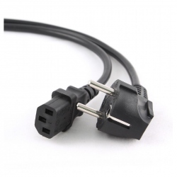
Power Cord...
Features German Schuko input and C13 output...
$1.56
-
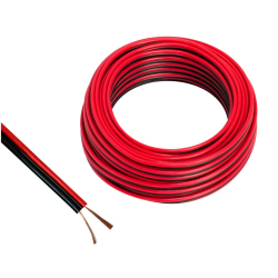
Red and...
Red and Black Audio Cable 2 x 2.5 mm (price per...
$0.62
-
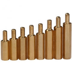
30*6 mm...
30*6 mm Metal M3 Hex Pillar
$0.48
-
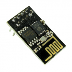
ESP-01 WiFi...
The ESP8266 Wifi module is a low cost and...
$4.20
-
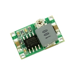
Mini-360...
This is a step-down DC-DC module that helps you...
$1.20
-
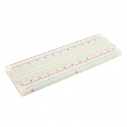
Breadboard...
This high quality 830 point breadboard is made...
$2.40
-
Adjustable...
This low voltage source can be adjusted, you...
$2.40
-
Pocket Multi...
Pocket Multitool See description for more...
$12.00
-
4 Channel...
This 4-channel bi-directional level translator...
$1.08
-
Plastic...
Plastic Hexagonal Nuts, Transparent, M3
$0.05