Dupa plasarea solicitării de comandă, in sectiunea Istoric puteti vedea cate solicitări de comandă mai avem de procesat inaintea dumneavoastra
Program de lucru: Luni - Vineri 8:30 - 17:30, pauza 12:30 - 13:30.
Se efectueaza lucrari de mentenanta la site si pot aparea erori. In cazul in care intampinati erori va rugam sa reincercati mai tarziu.
Ridicarea personala este disponibila pentru comenzile achitate in avans. Se pot ridica dupa ce sunt pregatite.
No products
 View larger


TB67H420FTG Dual/Single Motor Driver Carrier
0104110000072061
New product
This breakout board makes it easy to use Toshiba’s TB67H420FTG brushed DC motor driver, which can operate in either dual-channel mode for independent bidirectional control of two motors or single-channel mode for driving one motor with increased current. It has a wide operating voltage range of 10 V to 47 V and can deliver a continuous 1.7 A to each motor channel, or 3.4 A in single-channel mode. A configurable current chopping threshold allows the TB67H420 to actively limit the motor current, and it features built-in protection against under-voltage, over-current, and over-temperature conditions; our carrier board also adds reverse-voltage protection (up to 40 V).
See description for more details about the product.
Add to cart now!
This product is no longer in stock
- Write a review
- Remove this product from my favorite's list.
- Add this product to my list of favorites.
More info
Overview
The TB67H420FTG from Toshiba is an H-bridge motor driver IC that can be used for bidirectional control of one or two brushed DC motors at 10 V to 47 V. It can supply up to about 1.7 A continuously to each of two separate motors or about 3.4 A to a single motor, and it can tolerate peak currents up to 4.5 A per channel (dual) or 9 A (single) for a few seconds, making it a good choice for small- to medium-sized motors that run at higher voltages. The TB67H420FTG is a great IC, but its small surface-mount package makes it difficult for the typical student or hobbyist to use; our breakout board makes it easy to use with standard solderless breadboards and 0.1" perfboards. Since this board is a carrier for the TB67H420FTG, we recommend careful reading of the TB67H420FTG datasheet (460k pdf). The board ships populated with SMD components, including the TB67H420FTG and a reverse battery protection circuit.
Features
● Single- or dual-channel H-bridge motor driver (can drive one or two DC motors)
● Motor supply voltage: 10 V to 47 V
● Output current:
○ up to 1.7 A continuous (4.5 A peak) per motor in dual-channel mode
○ up to 3.4 A continuous (9 A peak) in single-channel mode
● Configurable current chopping actively limits motor current to 4.5 A per channel (dual) or 9 A (single) by default; can be lowered with external resistors or voltage sources
● No separate logic supply needed; inputs are 3V- and 5V-compatible
● Flexible input interface provides several options for control
● Under-voltage lockout and protection against over-current/short-circuit and over-temperature
● Open-load detection
● Carrier board adds reverse-voltage protection up to 40 V
● Active-low error outputs indicate over-current, over-temperature, or open-load condition
● Compact size (1.0" x 1.2")
● Exposed solderable ground pad below the driver IC on the bottom of the PCB
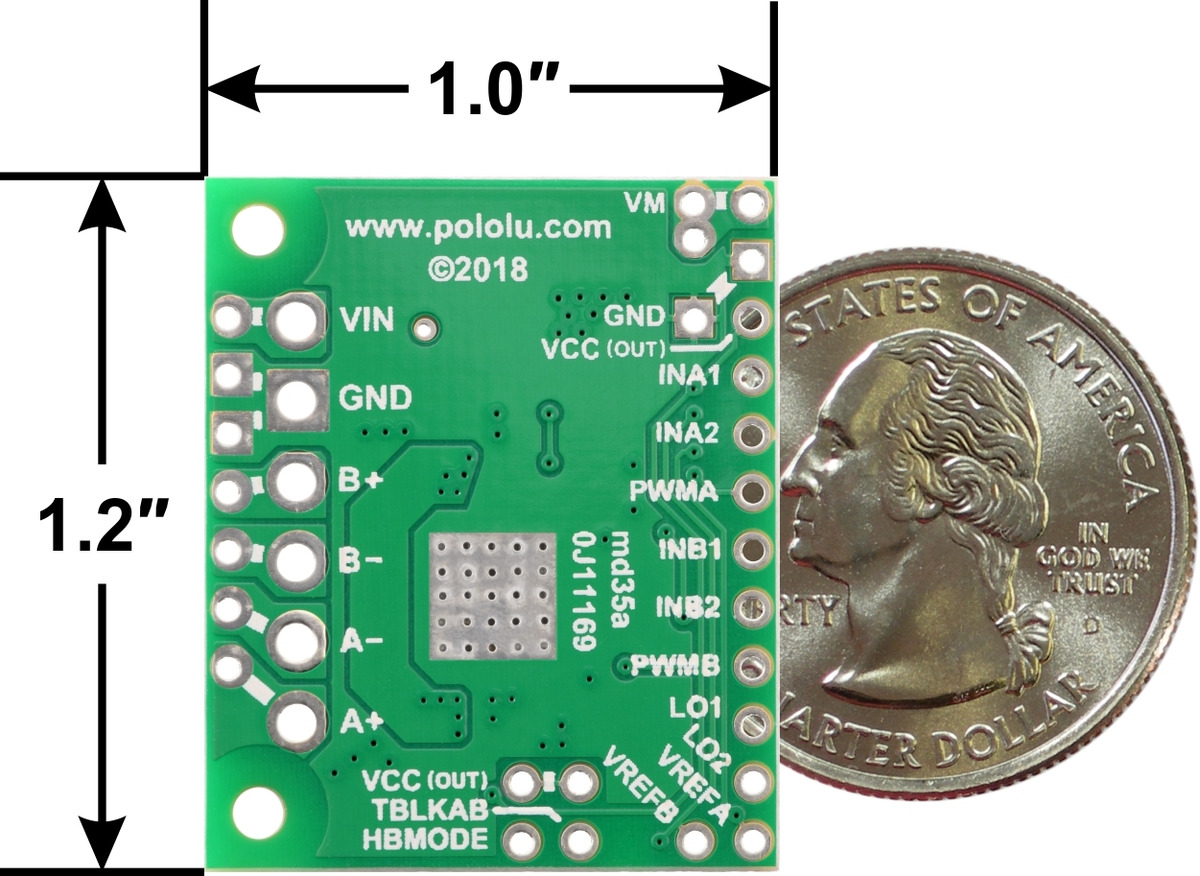
TB67H420FTG Dual/Single Motor Driver Carrier, bottom view with dimensions.
Note: the motor supply capacitors on this carrier are rated for 50 V; this is less margin than on most of our motor driver carriers, which have ICs with ratings of 40 V or less. Please keep this in mind if you want to push the high-voltage limit of this driver.
Using the motor driver
Motor and power connections are made on one side of the board and control connections are made on the other. The driver requires an operating voltage between 10 V and 47 V to be supplied to the power input, VIN. This input is reverse-protected up to 40 V, and the VM pin provides convenient access to the reverse-protected supply voltage.
In a typical application, three connections are used to control each motor driver channel: INx1 and INx2 to set the motor direction and PWMx to set the speed, resulting in drive-brake operation. The following simplified truth table shows how the driver operates with this control method:
| TB67H420FTG simplified truth table | |||||
| Inputs | Outputs | Operation | |||
| INx1 | INx2 | PWMx | x+ | x- | |
| 1 | 0 | PWM | PWM (H/L) | L | forward/brake at speed PWM % |
| 0 | 1 | L | PWM (H/L) | reverse/brake at speed PWM % | |
| 1 | 0 | 0 | L | L | brake low (outputs shorted to ground) |
| 0 | 1 | ||||
| 1 | 1 | X | |||
| 0 | 0 | X | Z | Z | coast (outputs floating/disconnected) (standby if all IN and PWM inputs are low) |
Note the special case when all six control inputs (INA1, INA2, PWMA, INB1, INB2, and PWMB) are low: this puts the driver into a lower-power standby mode and clears any active errors.
Alternatively, the control lines can be reduced to two pins per channel if PWM signals are applied directly to INx1 and INx2 with PWMx held high; this allows either drive/brake or drive/coast operation, depending on whether the non-PWMed input is held high or low, respectively. (Note that achieving drive/brake operation with this method requires inverted PWM signals; that is, with one IN pin PWMed and the other held high, the motor will drive while the PWM signal is low and brake while it is high.) The complete truth table below shows all possible combinations of the inputs and the driver outputs they produce:
| TB67H420FTG complete truth table | |||||
| Inputs | Outputs | Operation | |||
| PWMx | INx1 | INx2 | x+ | x- | |
| 0 | 0 | 0 | Z | Z | coast (standby if all IN and PWM inputs are low) |
| 1 | 0 | L | L | brake low | |
| 0 | 1 | ||||
| 1 | 1 | ||||
| 1 | 0 | 0 | Z | Z | coast |
| 1 | 0 | H | L | forward | |
| 0 | 1 | L | H | reverse | |
| 1 | 1 | L | L | brake low | |
By default, the TB67H420FTG runs in dual-channel mode and drives two motors independently, but it can optionally be configured to run in a paralleled single-channel mode, in which it can deliver about twice the current to a single motor. To select single-channel mode, connect the HBMODE pin to a logic high voltage; the adjacent VCC pin provides a convenient place to do so, either with a short piece of wire or with male header pins and a 0.1" shorting block.
In single-channel mode, the A+ and A− pins should be connected to form one motor output, and B+ and B− should be connected to form the other. The A inputs control the motor and the B inputs are not used; the driver enters standby mode when all three A control inputs are low.
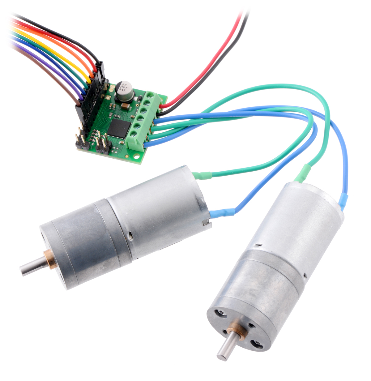
TB67H420FTG Dual/Single Motor Driver Carrier driving two motors in dual-channel mode.
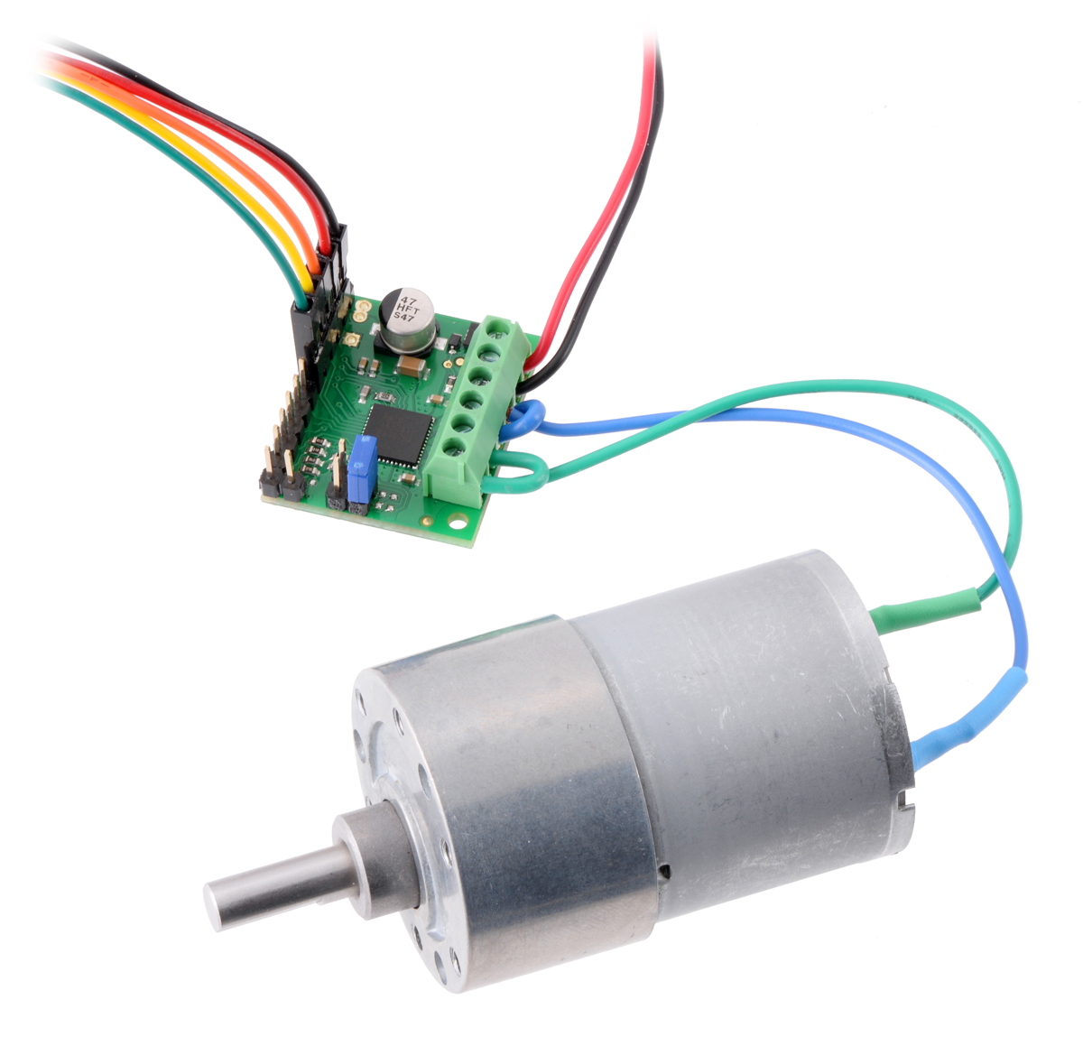
TB67H420FTG Dual/Single Motor Driver Carrier driving a motor in single-channel mode.
The TB67H420FTG can detect several fault (error) states that it reports by driving one or both of the LO pins low (the datasheet describes what each combination of LO1 and LO2 means). Otherwise, these pins are pulled up to VCC (5 V) by the board. Errors are latched, so the outputs will stay off and the error flag(s) will stay asserted until the error is cleared by toggling standby mode or disconnecting power to the driver.
Pinout
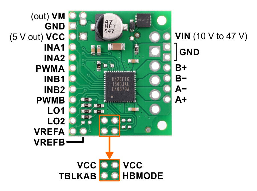
Pinout diagram of the TB67H420FTG Dual/Single Motor Driver Carrier.
Current limiting
The TB67H420FTG can actively limit the current through the motors by using a fixed-frequency PWM current regulation (current chopping). This carrier board connects voltage dividers to the VREFA and VREFB pins that set the reference voltage to about 3.6 V.
In dual channel mode, this results in a nominal current limit of 4.5 A per channel. You can lower the limit for each motor channel by adding a resistor between the corresponding VREF pin and GND, or you can apply a voltage (3.6 V max) directly to the VREF pin. The formula for the current chopping thresholds in dual-channel mode is Iout=VREF×1.25.
In single-channel mode, the default 3.6 V reference voltage results in a nominal single-channel current limit of 9 A. The formula for the current chopping threshold in single-channel mode is Iout=VREF×1.25.
Real-world power dissipation considerations
The TB67H420FTG datasheet recommends a maximum continuous current of 4.5 A, and this carrier board limits the motor current to the same amount. However, the chip by itself will typically overheat at lower currents. In our tests, we found that the chip was able to deliver 4.5 A per channel for only a few seconds before the chip’s thermal protection kicked in and disabled the motor outputs; a continuous current of about 1.7 A per channel was sustainable for many minutes without triggering a thermal shutdown. Driving only one channel at a time increases the sustainable current to almost 2.5 A per channel, and in single-channel mode, the driver can deliver about 3.4 A continuously without overheating.
The actual current you can deliver will depend on how well you can keep the motor driver cool. The carrier’s printed circuit board is designed to help with this by drawing heat out of the motor driver chip. PWMing the motor will introduce additional heating proportional to the frequency.
This product can get hot enough to burn you long before the chip overheats. Take care when handling this product and other components connected to it.
Schematic diagram
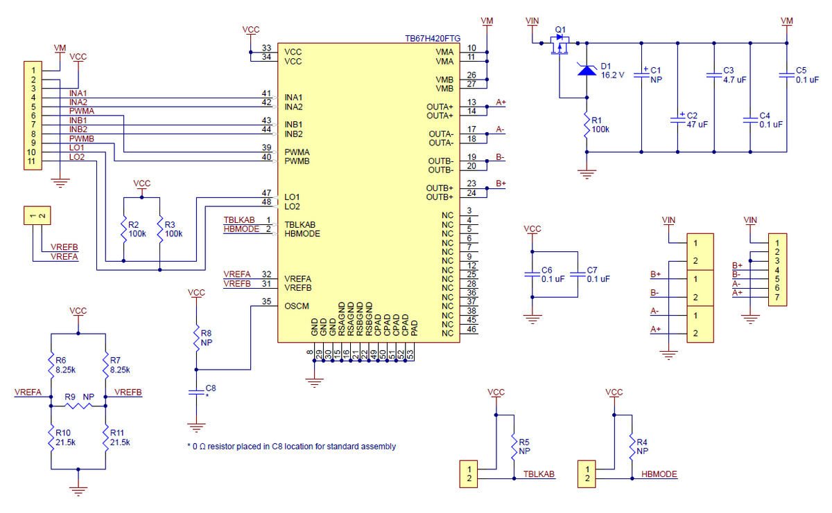
Schematic diagram of the TB67H420FTG Dual/Single Motor Driver Carrier.
This diagram is also available as a downloadable pdf: TB67H420FTG dual/single motor driver carrier schematic (158k pdf)
Specifications
Dimensions
| Size: | 1.2" x 1.0"1 |
| Weight: | 3.5 g1 |
General specifications
| Motor driver: | TB67H420FTG |
| Motor channels: | 2 |
| Minimum operating voltage: | 10 V |
| Maximum operating voltage: | 47 V2 |
| Continuous output current per channel: | 1.7 A |
| Continuous paralleled output current: | 3.4 A |
| Reverse voltage protection?: | Y2 |
Notes:
1 Without included hardware.
2 Note: Reverse voltage protection only works up to 40 V.
Don't delay. Buy today.
Add to cart now!
Reviews
Customers who bought this product also bought:
-
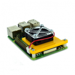
Raspberry Pi...
Raspberry Pi 4 Fan Mounting Bracket (Yellow and...
11,99 lei
-
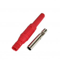
4mm Red...
4mm Red Copper Banana Female Plug Fully Enclosed
4,99 lei
-
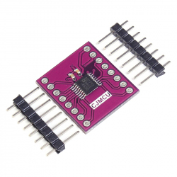
CJMCU...
This module is a 24-bit Sigma-Delta ADC...
34,99 lei
-

2 x 3p 2.54...
2 x 3p 2.54 mm Female Pin Header See...
0,69 lei
-
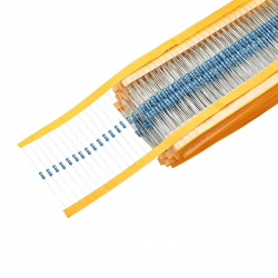
0.25W...
This set of resistors ideal for making...
14,99 lei
-
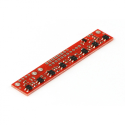
QTR-8A...
This sensor module has 8 IR LED/phototransistor...
39,99 lei
-
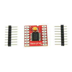
TB6612FNG...
This module can drive two DC motors at constant...
24,99 lei
-
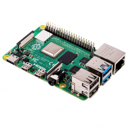
Raspberry Pi...
Genuine Product The latest series of...
302,42 lei
-
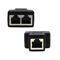
Splitter...
Splitter Dual RJ45 See description for more...
14,99 lei
-
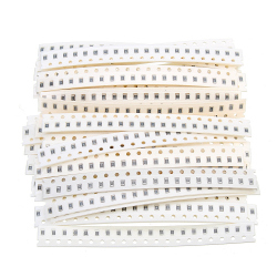
0805 SMD...
0805 SMD chip resistors with 5% precision for...
19,99 lei