Dupa plasarea solicitării de comandă, in sectiunea Istoric puteti vedea cate solicitări de comandă mai avem de procesat inaintea dumneavoastra
Program de lucru: Luni - Vineri 8:30 - 17:30, pauza 12:30 - 13:30.
Se efectueaza lucrari de mentenanta la site si pot aparea erori. In cazul in care intampinati erori va rugam sa reincercati mai tarziu.
Ridicarea personala este disponibila pentru comenzile achitate in avans. Se pot ridica dupa ce sunt pregatite.
No products
") View larger
View larger
")
")
")
")
")
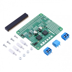
Pololu Dual G2 High-Power Motor Driver 18v18 for Raspberry Pi (Assembled)
0104110000047168
New product
This add-on board makes it easy to control two high-power DC motors with a Raspberry Pi. Its twin discrete MOSFET H-bridges support a wide 6.5 V to 30 V operating range and are efficient enough to deliver a continuous 18 A without a heat sink. The drivers offer basic current limiting functionality, and they accept ultrasonic PWM frequencies for quieter operation. The default pin mappings make it easy to get started, but they can be customized for more specialized applications.
With this module, you can control two DC motors with Raspberry Pi. Supports voltages from 6.5V to 30V and a maximum current of 18A without additional cooling. The module is assembled, does not require soldering.
See description for more details about the product.
Add to cart now!
1 Item
Warning: Last items in stock!
- Write a review
- Remove this product from my favorite's list.
- Add this product to my list of favorites.
More info
Overview
These G2 dual high-power motor drivers are add-on boards for the Raspberry Pi, featuring pairs of discrete MOSFET H-bridges designed to drive two large brushed DC motors. They are designed to mount on and plug into compatible Raspberry Pi boards (Model B+ or newer), including the Pi 3 Model B and Model A+.
_5.jpg)
The driver’s default configuration uses six GPIO pins to control the motor drivers, making use of the Raspberry Pi’s hardware PWM outputs, and it uses two additional pins to read status outputs from the drivers. However, the pin mappings can be customized if the defaults are not convenient, and pins for current sensing and limiting are accessible on the board for more advanced applications.
_1.jpg)
_2.jpg)
The board matches the Raspberry Pi HAT (Hardware Attached on Top) mechanical specification, although it does not conform to the full HAT specifications due to the lack of an ID EEPROM. (A footprint for adding your own EEPROM is available for applications where one would be useful; pull-ups on SDA, SCL, and WP are provided.) It is not practical to use this expansion board with the original Raspberry Pi Model A or Model B due to differences in their pinout and form factor.
These dual motor drivers are also available as Arduino shields. For single-channel versions in a more compact form factor, consider our High-Power Motor Drivers. For smaller, lower power, and lower cost alternatives designed for a Raspberry Pi, consider the Dual MC33926 Motor Driver for Raspberry Pi, Dual MAX14870 Motor Driver for Raspberry Pi, and DRV8835 Dual Motor Driver for Raspberry Pi.
Features common to all versions
• PWM operation up to 100 kHz
• Motor indicator LEDs show what the outputs are doing even when no motor is connected
• Integrated 5 V, 2.5 A switching step-down voltage regulator powers the Raspberry Pi base for single-supply operation
• Python library makes it easy to get started using this board as a motor driver expansion board
• GPIO pin mappings can be customized if the default mappings are not convenient
• Current sensing and limiting pins are exposed for advanced use
• Reverse-voltage protection
• Undervoltage shutdown
• Short circuit protection
Details
_3.jpg)
_4.jpg)
• Operating voltage: 6.5 V to 30 V (absolute maximum; not intended for use with 24 V batteries)
• Output current: 18 A continuous
• Active current limiting (chopping) with approximate default threshold of 50 A (can be adjusted lower)
Using the motor driver board
_6.jpg)
Power
An appropriate motor power supply should be connected to the motor driver’s large VIN and GND pads. The board includes a reverse-voltage protection circuit that helps prevent damage in case the motor power supply is connected backward. The reverse-protected input voltage can be accessed for use in other circuits through the two pins labeled VM on the left side of the board.
By default, the motor power supply also feeds a 5 V, 2.5 A switching step-down regulator that provides power to the connected Raspberry Pi. An ideal diode circuit makes it safe to have a different power supply connected to the Raspberry Pi through its USB Micro-B receptacle while the motor driver is connected and powered.
If you want to power the Raspberry Pi separately, the regulator can be disconnected by cutting two exposed traces on the board: one between the surface-mount pads labeled "VM" and "REG IN", and another between the two pins by the "REG OUT" label, as shown to the right. On the 24v14 and 24v18 versions, disconnecting the regulator increases the absolute maximum operating voltage of the board to 40 V.
_7.jpg)
Disconnecting the regulator on the Dual G2 High-Power Motor Driver for Raspberry Pi.
Default pin mappings
This table shows how the Raspberry Pi’s GPIO pins are used to interface with the motor drivers:
| RPi GPIO pin |
Motor driver pin | Description |
| 5 | Motor 1 FLT | Fault indicator: When the driver channel is functioning normally, this pin should be pulled high by the Raspberry Pi. In the event of a driver fault, FLT is driven low. See below for details. |
| 6 | Motor 2 FLT | |
| 12 | Motor 1 PWM | Motor speed input: A PWM (pulse-width modulation) signal on this pin corresponds to a PWM output on the corresponding channel’s motor outputs. When this pin is low, the motor brakes low. When it is high, the motor is on. The maximum allowed PWM frequency is 100 kHz. |
| 13 | Motor 2 PWM | |
| 22 | Motor 1 SLP | Inverted sleep input: This pin is pulled low by default, putting the motor driver channel into a low-current sleep mode and disabling the motor outputs (setting them to high impedance). SLP must be driven high to enable the motor channel. |
| 23 | Motor 2 SLP | |
| 24 | Motor 1 DIR | Motor direction input: When DIR is low, motor current flows from output A to output B; when DIR is high, current flows from B to A. |
| 25 | Motor 2 DIR |
Motor control options
With the PWM pin held low, both motor outputs will be held low (a brake operation). With PWM high, the motor outputs will be driven according to the DIR input. This allows two modes of operation: sign-magnitude, in which the PWM duty cycle controls the speed of the motor and DIR controls the direction, and locked-antiphase, in which a pulse-width-modulated signal is applied to the DIR pin with PWM held high.
In locked-antiphase operation, a low duty cycle drives the motor in one direction, and a high duty cycle drives the motor in the other direction; a 50% duty cycle turns the motor off. A successful locked-antiphase implementation depends on the motor inductance and switching frequency smoothing out the current (e.g. making the current zero in the 50% duty cycle case), so a high PWM frequency might be required.
| Inputs | Outputs | Operation | |||
| SLP | DIR | PWM | MxA | MxB | |
| 1 | 0 | PWM | PWM (H/L) | L | forward/brake at speed PWM % |
| 1 | 1 | PWM | L | PWM (H/L) | reverse/brake at speed PWM % |
| 1 | X | 0 | L | L | brake low (outputs shorted to ground) |
| 0 | X | X | Z | Z | coast (outputs off) |
PWM frequency
The motor driver supports PWM frequencies as high as 100 kHz, but note that switching losses in the driver will be proportional to the PWM frequency. Typically, around 20 kHz is a good choice for sign-magnitude operation since it is high enough to be ultrasonic, which results in quieter operation.
A pulse on the PWM pin must be high for a minimum duration of approximately 0.5 µs before the outputs turn on for the corresponding duration (any shorter input pulse does not produce a change on the outputs), so low duty cycles become unavailable at high frequencies. For example, at 100 kHz, the pulse period is 10 µs, and the minimum non-zero duty cycle achievable is 0.5/10, or 5%.
Fault conditions
The motor driver can detect several fault states that it reports by driving the FLT pin low; this is an open-drain output that should be pulled up to your system’s logic voltage. The detectable faults include short circuits on the outputs, under-voltage, and over-temperature. All of the faults disable the motor outputs but are not latched, meaning the driver will attempt to resume operation when the fault condition is removed (or after a delay of a few milliseconds in the case of the short circuit fault). The over-temperature fault provides a weak indication of the board being too hot, but it does not directly indicate the temperature of the MOSFETs, which are usually the first components to overheat, so you should not count on this fault to prevent damage from over-temperature conditions.
Remapping pins
All of the Raspberry Pi’s GPIO pins are broken out along a row of numbered through-holes just below the 40-pin GPIO connector. Each GPIO pin used by the board is connected from this row to the corresponding motor driver pin by a trace on the top side of the board spanning the pair of holes. If you want to remap one of these motor driver pins, you can cut its trace with a knife and then run a wire from the lower hole to a new GPIO pin.
_8.jpg)
Dual G2 High-Power Motor Driver for Raspberry Pi remapping example: moving M2DIR from GPIO pin 25 to pin 27.
Note that the default pin mappings were chosen so that the Raspberry Pi’s default GPIO pull-ups and pull-downs match the direction the motor driver pins are or should be pulled (up for SF, down for others); if you remap the motor driver pins without paying attention to this, you might encounter issues with pins being pulled the wrong way. See the Raspberry Pi documentation for more about the default GPIO states.
Current sensing and limiting
The motor driver exposes current sensing and limiting pins that are not connected to the Raspberry Pi, but they are accessible through their own through-holes in case you want to use them in a more advanced application.
The driver has the ability to limit the motor current through current chopping: once the motor drive current reaches a set threshold, the driver goes into brake mode (slow decay) for about 25 μs before applying power to drive the motor again. This makes it more practical to use the driver with a motor that might only draw a few amps while running but can draw many times that amount (tens of amps) when starting.
On this board (18v18), the nominal current limiting threshold is set to about 50 A by default. For each motor channel, you can lower the limit by connecting an additional resistor between the VREF pin and the adjacent GND pin; the graph below shows how the current limit relates to the VREF resistor value. For example, adding a 100 kΩ resistor between VREF and GND lowers the current limit to approximately 29 A. Note that the current limiting threshold is not highly precise, and is less accurate at especially low settings (indicated by the dashed portion of the curve).
_9.jpg)
Current sensing and limiting pins on the Dual G2 High Power Motor Driver for Raspberry Pi.
_10.png)
The driver’s current sense pins, labeled CS, output voltages proportional to the motor currents while the H-bridges are driving. The output voltage for this version is about 20 mV/A plus a small offset, which is typically about 50 mV.
Each CS output is only active while the corresponding H-bridge is in drive mode; it is inactive (low) when the channel is in brake mode (slow decay), which happens when the PWM input is low or when current limiting is active. Current will continue to circulate through the motor when the driver begins braking, but the voltage on the CS pin will not accurately reflect the motor current in brake mode. The CS voltage is used internally by the motor driver, so to avoid interfering with the driver’s operation, you should not add a capacitor to this pin or connect a load that draws more than a few mA from it.
Real-world power dissipation considerations
The MOSFETs can handle large current spikes for short durations (e.g. 100 A for a few milliseconds), and the driver’s current chopping will keep the average current under the set limit. The peak ratings are for quick transients (e.g. when a motor is first turned on), and the continuous rating is dependent on various conditions, such as the ambient temperature. PWMing the motor will introduce additional heating proportional to the frequency. The actual current you can deliver will depend on how well you can keep the motor driver cool. The driver’s printed circuit board is designed to draw heat out of the MOSFETs, but performance can be improved by adding a heat sink or air flow. For high-current installations, the motor and power supply wires should also be soldered directly instead of going through the supplied terminal blocks, which are rated for up to 16 A.
Warning: This motor driver has no over-temperature shut-off. An over-temperature or over-current condition can cause permanent damage to the motor driver. You might consider using either the driver’s integrated current sense output (with an external ADC) or an external current sensor to monitor your current draw.
This product can get hot enough to burn under normal operating conditions. Take care when handling this product and other components connected to it.
Specifications
Dimensions
| Size: | 65 mm x 56 mm |
| Weight: | 30 g1 |
General specifications
| Motor channels: | 2 |
| Minimum operating voltage: | 6.5 V |
| Maximum operating voltage: | 30 V2 |
| Continuous output current per channel: | 18 A3 |
| Maximum PWM frequency: | 100 kHz |
| Reverse voltage protection?: | Y |
| Partial kit?: | N |
Notes:
1 Without included mounting hardware.
2 Absolute maximum; higher voltages can permanently destroy the motor driver. Recommended maximum is approximately 24 V, which leaves a safety margin for ripple voltage on the supply line. Not recommended for use with 24V batteries.
3 Typical results at room temperature with both channels running at 90% duty cycle.
Don't delay, buy today.
Add to cart now!
Reviews
Customers who bought this product also bought:
-
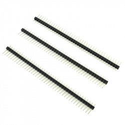
40p 2.54 mm...
This pin header is great for prototyping PCBs....
0,99 lei
-

90° 2.54 mm...
These 1 x 40 right angle male pin headers are...
1,49 lei
-
Dual MC33926...
This add-on board enables a compatible...
169,99 lei
-
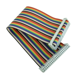
GPIO Cable...
GPIO Cable for Raspberry Pi See description...
6,50 lei
-
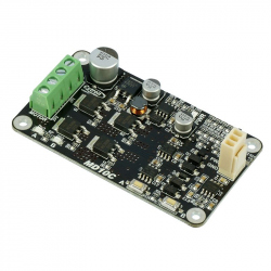
10Amp 5V-30V...
DC brushed motor is the most commonly used and...
64,99 lei
-
Pin Header...
Pin Header 2.54 mm for Raspberry Pi Zero (40p)...
3,99 lei
-
MicroSD Card...
This small SD card slot breakout board allows...
4,39 lei
-
12 V 30 A...
This product is an AC DC voltage source that...
99,89 lei
-
Raspberry Pi...
Original Product Raspberry Pi Pico W is a...
34,50 lei
-
Cooler for...
This cooler will help prevent your device from...
7,84 lei