Dupa plasarea solicitării de comandă, in sectiunea Istoric puteti vedea cate solicitări de comandă mai avem de procesat inaintea dumneavoastra
Program de lucru: Luni - Vineri 8:30 - 17:30, pauza 12:30 - 13:30.
Se efectueaza lucrari de mentenanta la site si pot aparea erori. In cazul in care intampinati erori va rugam sa reincercati mai tarziu.
Ridicarea personala este disponibila pentru comenzile achitate in avans. Se pot ridica dupa ce sunt pregatite.
No products
 View larger


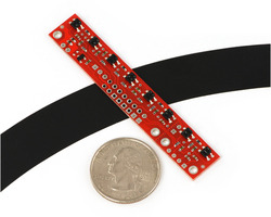
QTR-8RC Reflective Infrared Sensor Bar
0104110000010254
New product
This sensor module has 8 IR LED/phototransistor pairs mounted on a 0.375" pitch, making it a great detector for a line-following robot. Pairs of LEDs are arranged in series to halve current consumption, and a MOSFET allows the LEDs to be turned off for additional sensing or power-savings options. Each sensor provides a separate digital I/O-measurable output.
See description for more details about the product.
Add to cart now!
This product is no longer in stock
- Write a review
- Remove this product from my favorite's list.
- Add this product to my list of favorites.
More info
Description
Note: The QTR-8RC reflectance sensor array requires digital I/O lines to take readings. The similar QTR-8A reflectance sensor array is available with analog outputs, and the reflectance sensor is available individually as a QTR-1RC reflectance sensor or QTR-1A reflectance sensor.
Functional Description
The QTR-8RC reflectance sensor array is intended as a line sensor, but it can be used as a general-purpose proximity or reflectance sensor. The module is a convenient carrier for eight IR emitter and receiver (phototransistor) pairs evenly spaced at intervals of 0.375" (9.525 mm). To use a sensor, you must first charge the output node by applying a voltage to its OUT pin. You can then read the reflectance by withdrawing the externally supplied voltage and timing how long it takes the output voltage to decay due to the integrated phototransistor. Shorter decay time is an indication of greater reflection. This measurement approach has several advantages, especially when coupled with the ability of the QTR-8RC module to turn off LED power:
- No analog-to-digital converter (ADC) is required
- Improved sensitivity over voltage-divider analog output
- Parallel reading of multiple sensors is possible with most microcontrollers
- Parallel reading allows optimized use of LED power enable option
The outputs are all independent, but the LEDs are arranged in pairs to halve current consumption. The LEDs are controlled by a MOSFET with a gate normally pulled high, allowing the LEDs to be turned off by setting the MOSFET gate to a low voltage. Turning the LEDs off might be advantageous for limiting power consumption when the sensors are not in use or for varying the effective brightness of the LEDs through PWM control.
This sensor was designed to be used with the board parallel to the surface being sensed.
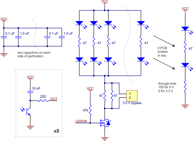
The LED current-limiting resistors for 5 V operation are arranged in two stages; this allows a simple bypass of one stage to enable operation at 3.3 V. The LED current is approximately 20–25 mA, making the total board consumption just under 100 mA. The schematic diagram of the module is shown below:
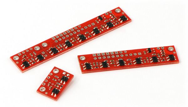
For a similar array with three sensors, consider our QTR-3RC reflectance sensor array. The sensors on the QTR-8RC are also available individually as the QTR-1RC reflectance sensor, and the QTR-L-1RC is an alternative designed to be used with the board perpendicular to the surface.
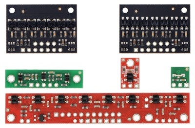
QTR sensor size comparison. Clockwise from top left: QTR-3RC, QTR-1RC, QTR-L-1RC, QTR-8RC
Specifications
- Dimensions: 2.95" x 0.5" x 0.125" (without header pins installed)
- Operating voltage: 3.3-5.0 V
- Supply current: 100 mA
- Output format: 8 digital I/O-compatible signals that can be read as a timed high pulse
- Optimal sensing distance: 0.125" (3 mm)
- Maximum recommended sensing distance: 0.375" (9.5 mm)
- Weight without header pins: 0.11 oz (3.09 g)
Interfacing the QTR-8RC Outputs to Digital I/O Lines
The QTR-8RC module has eight identical sensor outputs that, like the Parallax QTI, require a digital I/O line capable of driving the output line high and then measuring the time for the output voltage to decay. The typical sequence for reading a sensor is:
- Turn on IR LEDs (optional).
- Set the I/O line to an output and drive it high.
- Allow at least 10 μs for the sensor output to rise.
- Make the I/O line an input (high impedance).
- Measure the time for the voltage to decay by waiting for the I/O line to go low.
- Turn off IR LEDs (optional).
These steps can typically be executed in parallel on multiple I/O lines.
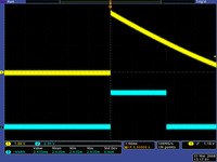
QTR-1RC output (yellow) when 1/8" above a black line and microcontroller timing of that output (blue)
With a strong reflectance, the decay time can be as low as several dozen microseconds; with no reflectance, the decay time can be up to a few milliseconds. The exact time of the decay depends on your microcontroller’s I/O line characteristics. Meaningful results can be available within 1 ms in typical cases (i.e. when not trying to measure subtle differences in low-reflectance scenarios), allowing up to 1 kHz sampling of all 8 sensors. If lower-frequency sampling is sufficient, substantial power savings can be realized by turning off the LEDs. For example, if a 100 Hz sampling rate is acceptable, the LEDs can be off 90% of the time, lowering average current consumption from 100 mA to 10 mA.
Breaking the Module in Two
If you don’t need or cannot fit all eight sensors, you can break off two sensors and still use all 8 sensors as two separate modules, as shown below. The PCB can be scored from both sides along the perforation and then bent until it snaps apart. Each of the two resulting pieces will function as an independent line sensor.
Included Components
This module ships with a 25-pin 0.1" header strip and a 100 Ohm through-hole resistor as shown below.
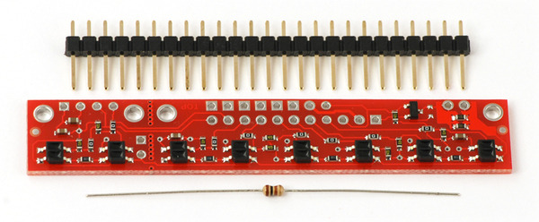
You can break the header strip into smaller pieces and solder them onto your reflectance sensor array as desired, or you can solder wires directly to the unit for a more compact installation. The pins on the module are arranged so that they can all be accessed using either an 11×1 strip or an 8×2 strip.
The resistor is required to make the two-sensor array functional after the original eight-sensor array is broken into two pieces. This resistor is only needed once the board has been broken.
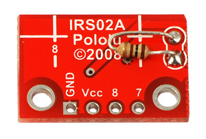
Solder the included resistor to the 2-sensor array piece as shown to make the separated piece functional
How it works in detail
For more information about how this sensor works, see the “How it works in detail” section of the QTR-1RC product page.
Don't delay. Buy today.
Add to cart now!
Reviews
Customers who bought this product also bought:
-
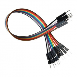
20 cm 10p...
20 cm 10p Male-Male Wires See description for...
4,49 lei
-
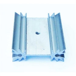
35 x 12 x 40...
35 x 12 x 40 mm Aluminum Radiator
2,49 lei
-
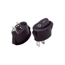
Oval On /...
Oval On / Off Switch See description for more...
1,19 lei
-

Relay with...
This 12 V relay module comes with...
24,99 lei
-
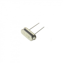
16 MHz...
This 16 MHz Quartz Crystal is used for precise...
1,40 lei
-
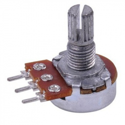
100k Mono...
100k Mono Potentiometer
1,49 lei
-
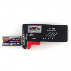
BT168...
This analog tester measures the current...
12,25 lei
-
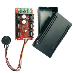
12 V 24 V 48...
The DC Motor Speed is a 9 - 50 V voltage...
49,99 lei
-
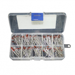
Zener Diode...
Zener Diode Kit (10 Kinds, 200 pcs) See...
29,99 lei
-
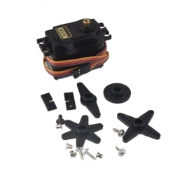
MG995...
MG995 servomotor that can be used for high...
29,99 lei