Dupa plasarea solicitării de comandă, in sectiunea Istoric puteti vedea cate solicitări de comandă mai avem de procesat inaintea dumneavoastra
Program de lucru: Luni - Vineri 8:30 - 17:30, pauza 12:30 - 13:30.
Se efectueaza lucrari de mentenanta la site si pot aparea erori. In cazul in care intampinati erori va rugam sa reincercati mai tarziu.
Ridicarea personala este disponibila pentru comenzile achitate in avans. Se pot ridica dupa ce sunt pregatite.
No products
") View larger
View larger
")
")
")
")
")
")
")
12V Motor with 64 CPR Encoder for 37D mm Metal Gearmotors (No Gearbox, Helical Pinion)
0104110000070401
New product
This is the motor and encoder portion of our 12V 37D mm metal gearmotors with 64 CPR encoders. It does not include a gearbox, but the pinion gear on the output shaft works with all of our helical pinion 37D mm gearmotor gearboxes, so this can be used as a replacement motor or encoder for those gearboxes. It is intended for use at 12 V, though the motor can begin rotating at voltages as low as 1 V.
Key specifications:
| voltage | no-load performance | stall extrapolation |
| 12 V | 10,000 RPM, 150 mA | 0.5 kg⋅cm (7 oz⋅in), 5.5 A |
See Description for more details about the product.
Don't delay, buy today. Add to cart now!
This product is no longer in stock
- Write a review
- Remove this product from my favorite's list.
- Add this product to my list of favorites.
More info
Overview
This motor with integrated 64 CPR (counts per revolution) quadrature encoder is intended as a replacement motor and encoder for our 37D mm metal gearmotors with helical pinion gears.
/a.jpg)
/b.jpg)
The 2mm output shaft has a non-removable pinion gear that works with all of our "Helical Pinion" 37D mm gearmotor gearboxes. Note that we do not sell the 37D mm gearboxes separately, but if you have a gearmotor with a damaged motor or encoder (or if you want to effectively add an encoder to a version without an encoder), you can transfer the gearbox to this replacement motor.
/c.jpg)
37D Gearmotor (Helical Pinion) with the gearbox removed showing the helical pinion gear and first mating gear.
The motor has a diameter of 34.5 mm (1.36 in) and a length of approximately 44 mm (1.7 in) from the top of the motor can to the bottom of the encoder. The top of the motor has six mounting holes evenly spaced around the outer edge threaded for M2.5 screws. These mounting holes form a regular hexagon, with the center of each hole located 13 mm from the center of the output shaft. The mounting holes have a depth of approximately 3.5 mm. See our 37D gearmotor dimension diagrams (461k pdf) for more details.
Gearmotor Options
You will typically want to combine this motor with a gearbox to give it a more appropriate combination of torque and speed (without a gearbox, it offers very high speed with very low torque). Our 37D mm line of metal gearmotors consist of this motor combined with different gearboxes. We do not carry the gearboxes by themselves, so unless you are looking at this as a replacement motor for a compatible gearbox you already have, we strongly recommend you consider getting a preassembled gearmotor with the gear ratio that best suits your project requirements.
| Rated Voltage | Stall Current | No-Load Current | Gear Ratio | No-Load Speed (RPM) | Extrapolated Stall Torque | Max Power (W) |
Without Encoder |
With Encoder |
|
| (kg ⋅ cm) | (oz ⋅ in) | ||||||||
| 12 V | 5.5 A | 0.15 A | 1:1 (no gearbox) | 10,000 |
0.5 |
7 | - | - | item #4750 |
| 6.3:1 | 1600 | 3.0 | 42 | 12 | item #4747 | item #4757 | |||
| 10:1 | 1000 | 4.9 | 68 | 12 | item #4748 | item #4758 | |||
| 19:1 | 540 | 8.5 | 120 | 12 | item #4741 | item #4751 | |||
| 30:1 | 330 | 14 | 190 | 12 | item #4742 | item #4752 | |||
| 50:1 | 200 | 21 | 290 | 10 | item #4743 | item #4753 | |||
| 70:1 | 150 | 27 | 380 | 8 | item #4744 | item #4754 | |||
| 100:1 | 100 | 34 | 470 | 8 | item #4745 | item #4755 | |||
| 131:1 | 76 | 45 | 630 | 6 | item #4746 | item #4756 | |||
| 150:1 | 67 | 49 | 680 | 6 | item #2829 | item #2828 | |||
/a.jpg)
/b.jpg)
Note: Stalling or overloading gearmotors can greatly decrease their lifetimes and even result in immediate damage. In order to avoid damaging the gearbox, we recommend keeping continuously applied loads under 10 kg-cm (150 oz-in), and the recommended upper limit for instantaneous torque is 25 kg-cm (350 oz-in). Stalls can also result in rapid (potentially on the order of seconds) thermal damage to the motor windings and brushes; a general recommendation for brushed DC motor operation is 25% or less of the stall current.
This motor is intended for use at 12 V, though in general, these kinds of motors can run at voltages above and below the nominal voltage (this motor can begin rotating at voltages as low as 1 V). Lower voltages might not be practical, and higher voltages could start negatively affecting the life of the motor.
The black plastic end cap is easily removable if you need to access the encoder or want to slightly reduce the overall motor size, but there is a little bit of base plastic that will remain, as can be seen in the pictures below that show this motor combined with a gearbox:
/c.jpg)
/d.jpg)
Using the encoder
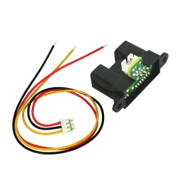
A two-channel Hall effect encoder is used to sense the rotation of a magnetic disk on a rear protrusion of the motor shaft. The quadrature encoder provides a resolution of 64 counts per revolution of the motor shaft when counting both edges of both channels. To compute the counts per revolution of the gearbox output, multiply the gear ratio by 64. The motor/encoder has six color-coded, 8″ (20 cm) leads terminated by a 1×6 female header with a 0.1″ pitch, as shown in the main product picture. This header works with standard 0.1″ male headers and our male jumper and precrimped wires. If this header is not convenient for your application, you can pull the crimped wires out of the header or cut the header off. The following table describes the wire functions:
| Color | Function |
| Red | motor power (connects to one motor terminal) |
| Black | motor power (connects to the other motor terminal) |
| Green | encoder GND |
| Blue | encoder Vcc (3.5 – 20 V) |
| Yellow | encoder A output |
| White | encoder B output |
/f.jpg)
37D mm metal gearmotor with 64 CPR encoder (with end cap removed).
/d.jpg)
The Hall sensor requires an input voltage, Vcc, between 3.5 and 20 V and draws a maximum of 10 mA. The A and B outputs are square waves from 0 V to Vcc approximately 90° out of phase. The frequency of the transitions tells you the speed of the motor, and the order of the transitions tells you the direction. The following oscilloscope capture shows the A and B (yellow and white) encoder outputs using a motor voltage of 12 V and a Hall sensor Vcc of 5 V:
/e.jpg)
Encoder A and B outputs for 37D mm metal gearmotor with 64 CPR encoder (motor running at 12 V).
By counting both the rising and falling edges of both the A and B outputs, it is possible to get 64 counts per revolution of the motor shaft. Using just a single edge of one channel results in 16 counts per revolution of the motor shaft, so the frequency of the A output in the above oscilloscope capture is 16 times the motor rotation frequency.
Selecting the Right Gearmotor
We offer a wide selection of metal gearmotors that offer different combinations of speed and torque. Our metal gearmotor comparison table can help you find the motor that best meets your project’s requirements.
/07.jpg)
Don't delay, buy today.
Add to cart now!
Reviews
Customers who bought this product also bought:
-
GP2Y0A02YK0F...
Infrared remote sensor from Sharp. The...
57,99 lei
-
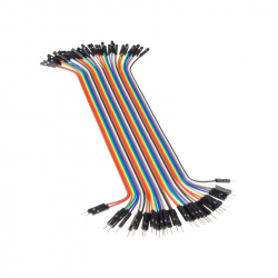
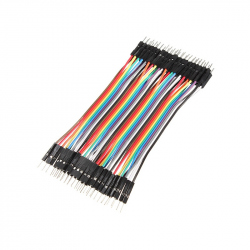
20 cm 40p...
Ideal wires for making connections for...
7,99 lei
-

Plusivo...
250 pcs Plusivo Resistor Kit See description...
14,99 lei
-
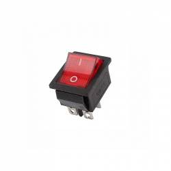
Large On /...
Large On / Off Switch with LED See description...
1,99 lei
-
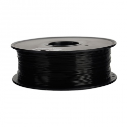
1.75 mm, 1...
You can easily print with this PLA filament and...
69,99 lei
-
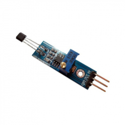
Hall Sensor...
Hall sensor module YS-27 that can be used to...
6,49 lei
-
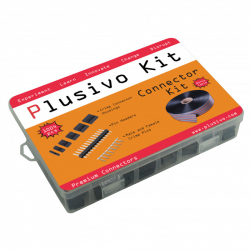
Connector...
Complete Connector Kit: single row pin...
59,99 lei
-
10 cm 40p...
Ideal wires for making connections between...
4,99 lei
-
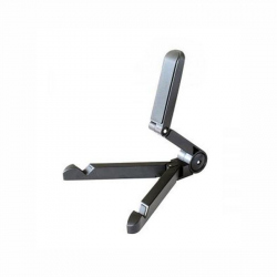
CY1486...
CY1486 Smartphone / Tablet Holder See...
14,99 lei
-
20 cm 40p...
Ideal wires for making connections between...
7,99 lei