Dupa plasarea solicitării de comandă, in sectiunea Istoric puteti vedea cate solicitări de comandă mai avem de procesat inaintea dumneavoastra
Program de lucru: Luni - Vineri 8:30 - 17:30, pauza 12:30 - 13:30.
Se efectueaza lucrari de mentenanta la site si pot aparea erori. In cazul in care intampinati erori va rugam sa reincercati mai tarziu.
Ridicarea personala este disponibila pentru comenzile achitate in avans. Se pot ridica dupa ce sunt pregatite.
No products
 View larger


VL53L1X Time-of-Flight Distance Sensor Carrier with Voltage Regulator, 400cm Max
0104110000044976
New product
This sensor is a carrier/breakout board for ST’s VL53L1X laser-ranging sensor, which offers fast and accurate ranging up to 4 m. It uses the time of flight (ToF) of invisible, eye-safe laser pulses to measure absolute distances independent of ambient lighting conditions and target characteristics like color, shape, and texture (though these things will affect the maximum range). The VL53L1X also features a programmable region of interest (ROI), so the full field of view can be reduced or divided into multiple zones. Distance measurements can be read through a digital I2C interface. The board includes a 2.8 V linear regulator and level-shifters that allow it to work over an input voltage range of 2.6 V to 5.5 V, and the 0.1" pin spacing makes it easy to use with standard solderless breadboards and 0.1" perfboards.
See description for more details about the product.
Add to cart now!
This product is no longer in stock
- Write a review
- Remove this product from my favorite's list.
- Add this product to my list of favorites.
More info
Overview
The VL53L1X from ST Microelectronics is a long-distance ranging time-of-flight (TOF) sensor integrated into a compact module. This board is a carrier for the VL53L1X, so we recommend careful reading of the VL53L1X datasheet (1MB pdf) before using this product.
The VL53L1X is effectively a tiny, self-contained lidar system featuring an integrated 940 nm Class 1 laser, which is invisible and eye-safe. Unlike conventional IR sensors that use the intensity of reflected light to estimate the distance to an object, the VL53L1X uses ST’s FlightSense technology to precisely measure how long it takes for emitted pulses of infrared laser light to reach the nearest object and be reflected back to a detector. This approach ensures absolute distance measurements independent of ambient lighting conditions and target characteristics (e.g. color, shape, texture, and reflectivity), though these external conditions do affect the maximum range of the sensor, as do the sensor configuration settings.
Under favorable conditions, such as low ambient light with a high-reflectivity target, the sensor can report distances up to 4 m (13 ft) with 1 mm resolution. See the datasheet for more information on how various external conditions and sensor configurations affect things like maximum range, repeatability, and ranging error. The minimum ranging distance is 4 cm; inside of this range, the sensor will still detect a target, but the measurement will not be accurate. Ranging measurements are available through the sensor’s I2C (TWI) interface, which is also used to configure sensor settings, and the sensor provides two additional pins: a shutdown input and an interrupt output.
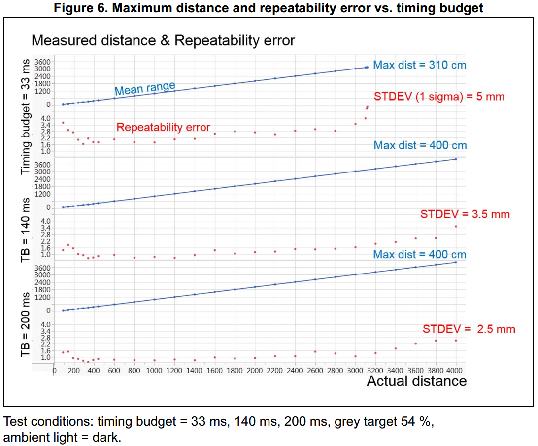
The VL53L1X offers three distance modes: short, medium, and long. Long distance mode allows the longest possible ranging distance of 4 m, but the maximum range is significantly affected by ambient light. Short distance mode is mostly immune to ambient light, but the maximum ranging distance is typically limited to 1.3 m (4.4 ft). The maximum sampling rate in short distance mode is 50 Hz while the maximum sampling rate for medium and long distance modes is 30 Hz. Performance can be improved in all modes by using lower sampling rates and longer timing budgets (as can be seen in the figure above).
For advanced applications, the VL53L1X supports configurable thresholds that can be used to trigger interrupts when a target is detected below a certain distance, beyond a certain distance, outside of a range, or within a range. It also supports an alternate detection mode that generates an interrupt when no target is present. Additionally, unlike its predecessors, the VL53L1X supports a configurable region of interest (ROI) within its full 16×16 sensing array, allowing you to reduce the field of view (FoV). With all 265 detection elements enabled, the FoV is 27°. An “Autonomous Low Power” mode that is specially tuned for advanced presence detection is available. This mode allows for significant system power saving by switching off or waking up the host automatically when a human or object is detected within the configured distance thresholds in the region of interest.
The VL53L1X is a great IC, but its small, leadless, LGA package makes it difficult for the typical student or hobbyist to use. It also operates at a recommended voltage of 2.8 V, which can make interfacing difficult for microcontrollers operating at 3.3 V or 5 V. Our breakout board addresses these issues, making it easier to get started using the sensor, while keeping the overall size as small as possible.
The carrier board includes a low-dropout linear voltage regulator that provides the 2.8 V required by the VL53L1X and allows the sensor to be powered from a 2.6 V to 5.5 V supply. The regulator output is available on the VDD pin and can supply almost 150 mA to external devices. The breakout board also includes a circuit that shifts the I2C clock and data lines to the same logic voltage level as the supplied VIN, making it simple to interface the board with 3.3 V or 5 V systems, and the board’s 0.1" pin spacing makes it easy to use with standard solderless breadboards and 0.1" perfboards. The board ships fully populated with its SMD components, including the VL53L1X, as shown in the product picture.
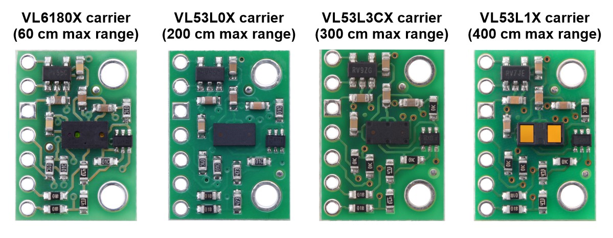
For for similar but shorter-range sensors, see our 200 cm VL53L0X carrier and 60 cm VL6180X carrier. Both of these are physical drop-in replacements for the VL53L1X carrier, but they have different APIs, so software for the VL53L1X will need to be rewritten to work with the VL53L0X or VL6180X.
Features and specifications
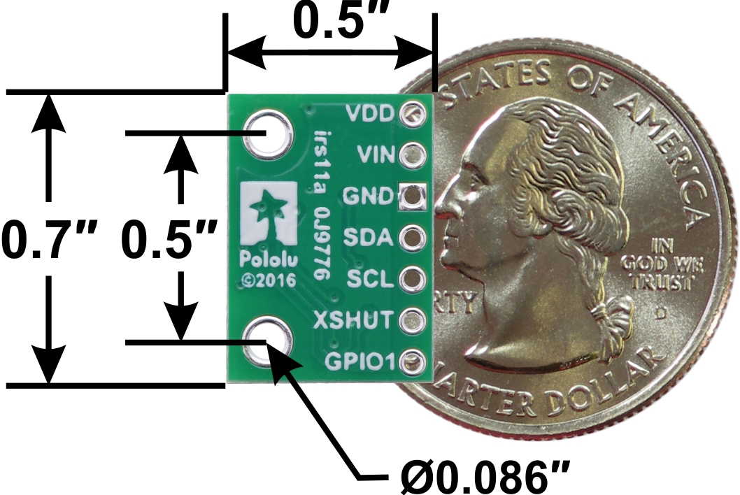
• Dimensions: 0.5" x 0.7" x 0.085" (13 mm x 18 mm x 2 mm)
• Weight without header pins: 0.5 g (0.02 oz)
• Operating voltage: 2.6 V to 5.5 V
• Supply current: ~15 mA (typical average during active ranging at max sampling rate)
○ Varies with configuration, target, and environment; peak current can reach 40 mA
• Fast and accurate ranging with three distance mode options:
○ Short: up to ~130 cm, 50 Hz max sampling rate; this mode is the most immune to interference from ambient light
○ Medium: up to ~300 cm in the dark, 30 Hz max sampling rate
○ Long: up to 400 cm in the dark, 30 Hz max sampling rate
• Minimum range: 4 cm (objects under this range are detected, but measurements are not accurate)
• Emitter: 940 nm invisible Class 1 VCSEL (vertical cavity surface-emitting laser) – eye-safe
• Detector: 16x16 SPAD (single photon avalanche diode) receiving array with integrated lens
○ Typical full field of view (FoV): 27°
○ Programmable region of interest (ROI) size on the receiving array, allowing the sensor FoV to be reduced
○ Programmable ROI position on the receiving array, allowing multizone operation control from the host
• Configurable detection interrupt thresholds for implementing
○ target closer than threshold
○ target farther than threshold
○ target within distance window
○ target outside of distance window
○ no target
• Output format (I2C): 16-bit distance reading (in millimeters)
Using the VL53L1X
Connections
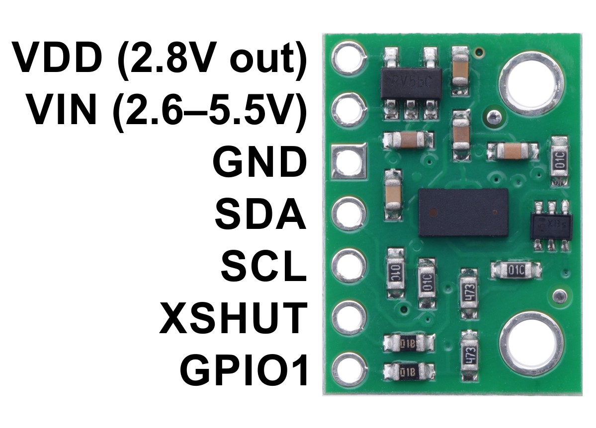
At least four connections are necessary to use the VL53L1X board: VIN, GND, SCL, and SDA. The VIN pin should be connected to a 2.6 V to 5.5 V source, and GND should be connected to 0 volts. An on-board linear voltage regulator converts VIN to a 2.8 V supply for the VL53L1X IC. Note that if your input voltage is under 3.5 V, you can connect it directly to VDD instead to bypass the regulator; in this configuration, VIN should remain disconnected.
The I2C pins, SCL and SDA, are connected to built-in level-shifters that make them safe to use at voltages over 2.8 V; they should be connected to an I2C bus operating at the same logic level as VIN.
The XSHUT pin is an input and the GPIO1 pin is an open-drain output; both pins are pulled up to 2.8 V by the board. They are not connected to level-shifters on the board and are not 5V-tolerant, but they are usable as-is with many 3.3 V and 5 V microcontrollers: the microcontroller can read the GPIO1 output as long as its logic high threshold is below 2.8 V, and the microcontroller can alternate its own output between low and high-impedance states to drive the XSHUT pin.
Pinout
| PIN | Description |
| VDD | Regulated 2.8 V output. Almost 150 mA is available to power external components. (If you want to bypass the internal regulator, you can instead use this pin as an input for voltages between 2.6 V and 3.5 V with VIN disconnected.) |
| VIN | This is the main 2.6 V to 5.5 V power supply connection. The SCL and SDA level shifters pull the I2C lines high to this level. |
| GND | The ground (0 V) connection for your power supply. Your I2C control source must also share a common ground with this board. |
| SDA | Level-shifted I2C data line: HIGH is VIN, LOW is 0 V |
| SCL | Level-shifted I2C clock line: HIGH is VIN, LOW is 0 V |
| XSHUT | This pin is an active-low shutdown input; the board pulls it up to VDD to enable the sensor by default. Driving this pin low puts the sensor into hardware standby. This input is not level-shifted. |
| GPIO1 | Programmable interrupt output (VDD logic level). This output is not level-shifted. |
Schematic diagram
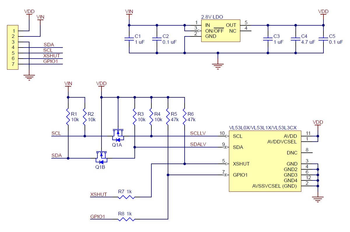
The above schematic shows the additional components the carrier board incorporates to make the VL53L1 easier to use, including the voltage regulator that allows the board to be powered from a 2.6 V to 5.5 V supply and the level-shifter circuit that allows for I2C communication at the same logic voltage level as VIN. This schematic is also available as a downloadable PDF (108k pdf).
I2C communication
The VL53L1X can be configured and its distance readings can be queried through the I2C bus. Level shifters on the I²C clock (SCL) and data (SDA) lines enable I2C communication with microcontrollers operating at the same voltage as VIN (2.6 V to 5.5 V). A detailed explanation of the I2C interface on the VL53L1X can be found in its datasheet (1MB pdf), and more detailed information about I2C in general can be found in NXP’s I2C-bus specification (1MB pdf).
The sensor’s 7-bit slave address defaults to 0101001b on power-up. It can be changed to any other value by writing one of the device configuration registers, but the new address only applies until the sensor is reset or powered off. ST provides an application note (196k pdf) that describes how to use multiple VL53L0X sensors on the same I2C bus by individually bringing each sensor out of reset and assigning it a unique address, and the approach can be easily adapted to apply to the VL53L1X instead.
The I2C interface on the VL53L1X is compliant with the I2C fast mode (400 kHz) standard. In our tests of the board, we were able to communicate with the chip at clock frequencies up to 400 kHz; higher frequencies might work but were not tested.
Sensor configuration and control
In contrast with the information available for many other devices, ST has not publicly released a register map and descriptions or other documentation about configuring and controlling the VL53L1X. Instead, communication with the sensor is intended to be done through ST’s VL53L1X API (STSW-IMG007), a set of C functions that take care of the low-level interfacing. To use the VL53L1X, you can customize the API to run on a host platform of your choice using the information in the API documentation. Alternatively, it is possible to use the API source code as a guide for your own implementation.
Sample code
We have written a basic Arduino library for the VL53L1X, which can be used as an alternative to ST’s official API for interfacing this sensor with an Arduino or Arduino-compatible controller. The library makes it simple to configure the VL53L1X and read the distance data through I2C. It also includes example sketches that show you how to use the library.
We also have an implementation of ST’s VL53L1X API for Arduino available, including an example sketch. Compared to our library, the API has a more complicated interface and uses more storage and memory, but it offers some advanced functionality that our library does not provide and has more robust error checking. Consider using the API for advanced applications, especially when storage and memory are less of an issue.
Specifications
Dimensions
| Size: | 0.5" x 0.7" x 0.085"1 |
| Weight: | 0.5 g1 |
General specifications
| Resolution: | 1 mm |
| Maximum range: | 400 cm2 |
| Minimum range: | 4 cm3 |
| Interface: | I2C |
| Minimum operating voltage: | 2.6 V |
| Maximum operating voltage: | 5.5 V |
| Supply current: | 15 mA4 |
Notes:
1 Without included optional headers.
2 Effective range depends on configuration, target, and environment.
3 The sensor will still detect targets closer than this, but the measurement will not be accurate.
4 Typical average during active ranging at 50 Hz; varies with configuration, target, and environment. Peak current can reach 40 mA.
Don't delay, buy today.
Add to cart now!
Reviews
Customers who bought this product also bought:
-
RPI NOIR...
RPI NOIR CAMERA BOARD. - Raspberry Pi NoIR...
197,99 lei
-
5V, 15A...
This synchronous switching step-down (or buck)...
187,00 lei
-
12 V...
12 V 50x50x12 mm Fan
7,99 lei
-
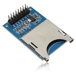
SD Card Reader
SD Card Reader
5,99 lei
-
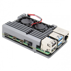
Heatsink...
Heatsink Case for Raspberry Pi 4 (Silver Color,...
74,99 lei
-
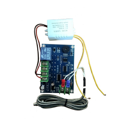
W1315...
Technical parameters Specification model:...
59,99 lei
-
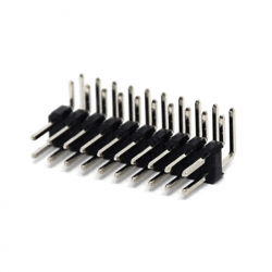
2 x 10p 2.54...
2 x 10p 2.54 mm 90° Male Pin Header See...
1,49 lei
-
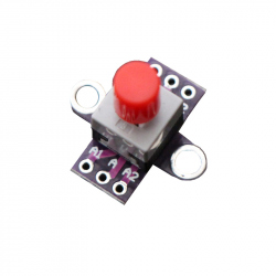
Lock Switch...
Lock Switch Module (Unsoldered)
1,99 lei
-

Battery...
Battery Support 2x18650
6,99 lei
-
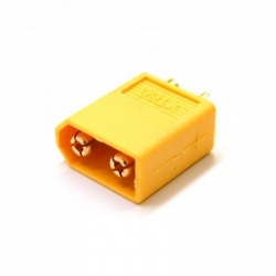
Male XT60...
Made from high-temp Nylon and gold plated...
4,91 lei