Dupa plasarea solicitării de comandă, in sectiunea Istoric puteti vedea cate solicitări de comandă mai avem de procesat inaintea dumneavoastra
Program de lucru: Luni - Vineri 8:30 - 17:30, pauza 12:30 - 13:30.
Se efectueaza lucrari de mentenanta la site si pot aparea erori. In cazul in care intampinati erori va rugam sa reincercati mai tarziu.
Ridicarea personala este disponibila pentru comenzile achitate in avans. Se pot ridica dupa ce sunt pregatite.
No products
 View larger


Zumo Reflective Infrared Sensor Bar
0104110000010261
New product
This reflectance sensor module is designed for use with the Zumo shield for Arduino. It has six IR LED/phototransistor pairs that can be used for line following or edge detection; each sensor provides an independent, digital I/O-measurable output. The array draws approximately 40 mA when the emitters are on, and an optional input allows the emitters to be turned off for additional sensing or power-saving options.
See description for more details about the product.
Add to cart now!
1 Item
Warning: Last items in stock!
- Write a review
- Remove this product from my favorite's list.
- Add this product to my list of favorites.
More info
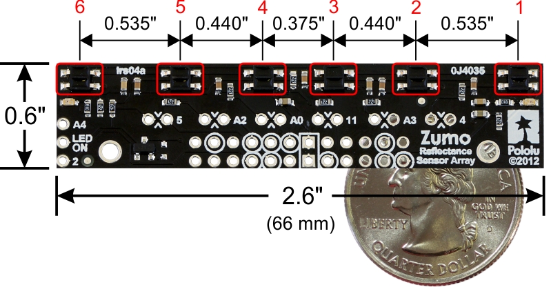
Zumo reflectance sensor array with labeled sensors and dimensions.
Overview
The Zumo reflectance sensor array provides an easy way to add line sensing or edge detection to a Zumo robot. It features six separate reflectance sensors, each consisting of an IR emitter coupled with a phototransistor that responds based on how much emitter light is reflected back to it. The two outside sensors are positioned at the very edges of the module to maximize their usefulness as edge detectors (e.g. for seeing the white edge of a sumo ring) while the four inner sensors are closer together for better detecting lines. This sensor is included with the assembled version of the Zumo robot, but not with the kit version.
The sensor array plugs into the front expansion header of the Zumo shield, which provides it with power and the necessary I/O connections. The default I/O connections are to pins that are otherwise unused by the Zumo shield, but the sensor module makes it possible to remap these pins or disconnect specific sensors altogether to free up I/O lines. Please see the Zumo Shield user’s guide for detailed information about assembly and use with the Zumo robot.
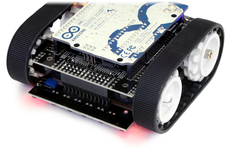
Zumo reflectance sensor array on a Zumo robot.
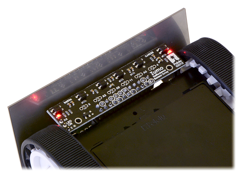
Zumo reflectance sensor array on a Zumo robot, bottom view.
How it works
The array uses the same sensor modules as our QTR reflectance sensors and has the same principle of operation as our QTR-8RC version. The procedure for reading each sensor is as follows:
- Turn on IR LEDs (optional).
- Make the I/O line connected to that sensor an output and drive it high.
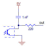
- Wait several microseconds to give the 1 nF capacitor node time to reach 5 V.
- Make the I/O line an input (with internal pull-up disabled).
- Measure the time for the voltage to decay by waiting for the I/O line to go low.
- Turn off IR LEDs (optional).
These steps can typically be executed in parallel for all six sensors. Our Zumo Arduino library provides functions for reading the sensors and controlling the emitters (as well as high-level functions for taking calibrated readings and determining the position of a line), so you do not have to program this sequence of steps yourself.
With a strong reflectance, the decay time can be as low as several dozen microseconds; with no reflectance, the decay time can be up to a few milliseconds. Meaningful results can be available within 1 ms in typical cases (i.e. when not trying to measure subtle differences in low-reflectance scenarios), allowing up to 1 kHz sampling of all 6 sensors. If lower-frequency sampling is sufficient, substantial power savings can be realized by turning off the LEDs. For example, if a 100 Hz sampling rate is acceptable, the LEDs can be off 90% of the time, lowering average current consumption from 40 mA to 4 mA.
To minimize the required emitter current, the IR LEDs are arranged in two parallel chains of three and powered from the Zumo shield’s boosted 7.45 V. Each chain of emitters is wired in series with a red LED, making it possible to tell when current is flowing through that chain (it is not possible to tell if the IR LEDs are on by looking at them with the unaided eye). All of the IR emitter LEDs are controlled by a single MOSFET that is gated by a digital LEDON input that enables the emitters when left disconnected or driven high. If this input is driven low, the emitters are disabled. Turning the LEDs off might be advantageous for limiting power consumption when the sensors are not in use or for varying the effective brightness of the LEDs through PWM control. Additionally, reading the sensors with the emitters turned off makes it possible to detect (and potentially compensate for) any ambient IR that might be interfering with readings. When the emitters are on, the sensor array draws approximately 40 mA.
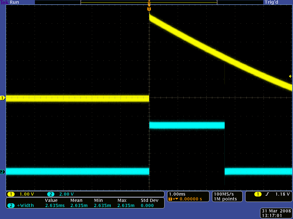
QTR-1RC output (yellow) when 1/8" above a black line and microcontroller timing of that output (blue).
Schematic diagram
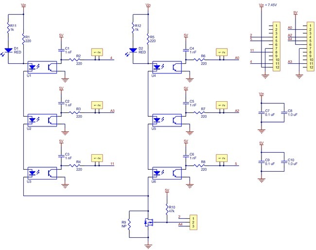
This schematic diagram is also available as a downloadable pdf (211k pdf).
Specifications
Dimensions
| Size: | 2.6" x 0.6"1 |
| Weight: | 3.6 g2 |
General specifications
| Supply current: | 40 mA |
Notes:
1 Without header pins.
2 Without included hardware. Weight becomes 8.1 g with included male and female headers.
Don't delay. Buy today.
Add to cart now!
Reviews
Customers who bought this product also bought:
-
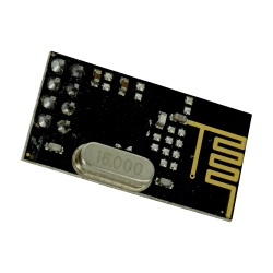
nRF24L01 2.4...
The NRF24L01 is a single-chip transceiver chip...
$1.68
-
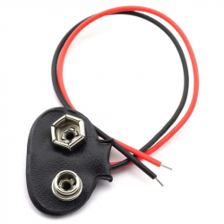
9v Battery...
This product is used to connect a 9 volt...
$0.31
-
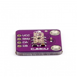
AEDR-8300...
This module is based on the AEDR-8300 optical...
$5.01
-
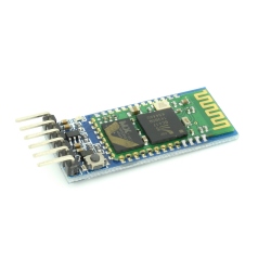
HC-05 Master...
The HC-05 Bluetooth module is a high...
$6.74
-
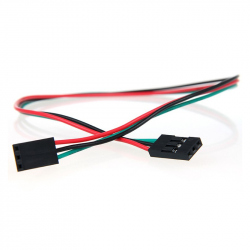
3p 20 cm...
This 3-pin female wire jumper can be used for...
$0.36
-
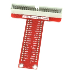
GPIO Adapter...
GPIO Adapter for Raspberry Pi See description...
$2.40
-
Mini...
The AMS1117-3.3 V voltage regulator module is...
$0.85
-
18650 XTAR...
Charging current: 0, 5A Charging voltage: 4,...
$13.20
-
LCD 2004...
LCD 2004 with Blue Backlight See description...
$7.20
-
GA12-N20...
This small and easy, but powerful motor reducer...
$3.60