Dupa plasarea solicitării de comandă, in sectiunea Istoric puteti vedea cate solicitări de comandă mai avem de procesat inaintea dumneavoastra
Program de lucru: Luni - Vineri 8:30 - 17:30, pauza 12:30 - 13:30.
Se efectueaza lucrari de mentenanta la site si pot aparea erori. In cazul in care intampinati erori va rugam sa reincercati mai tarziu.
Ridicarea personala este disponibila pentru comenzile achitate in avans. Se pot ridica dupa ce sunt pregatite.
No products
 View larger


A4988 Stepper Motor Driver Carrier Pololu
0104110000051936
New product
This breakout board for Allegro’s A4988 microstepping bipolar stepper motor driver features adjustable current limiting, over-current and over-temperature protection, and five different microstep resolutions (down to 1/16-step). It operates from 8 V to 35 V and can deliver up to approximately 1 A per phase without a heat sink or forced air flow (it is rated for 2 A per coil with sufficient additional cooling). This board ships with 0.1" male header pins included but not soldered in.
See description for more details about the product.
Add to cart now!
This product is no longer in stock
- Write a review
- Remove this product from my favorite's list.
- Add this product to my list of favorites.
More info
Overview
This product is a carrier board or breakout board for Allegro’s A4988 DMOS Microstepping Driver with Translator and Overcurrent Protection; we therefore recommend careful reading of the A4988 datasheet (1MB pdf) before using this product. This stepper motor driver lets you control one bipolar stepper motor at up to 2 A output current per coil (see the Power Dissipation Considerations section below for more information). Here are some of the driver’s key features:
• Simple step and direction control interface
• Five different step resolutions: full-step, half-step, quarter-step, eighth-step, and sixteenth-step
• Adjustable current control lets you set the maximum current output with a potentiometer, which lets you use voltages above your stepper motor’s rated voltage to achieve higher step rates
• Intelligent chopping control that automatically selects the correct current decay mode (fast decay or slow decay)
• Over-temperature thermal shutdown, under-voltage lockout, and crossover-current protection
• Short-to-ground and shorted-load protection
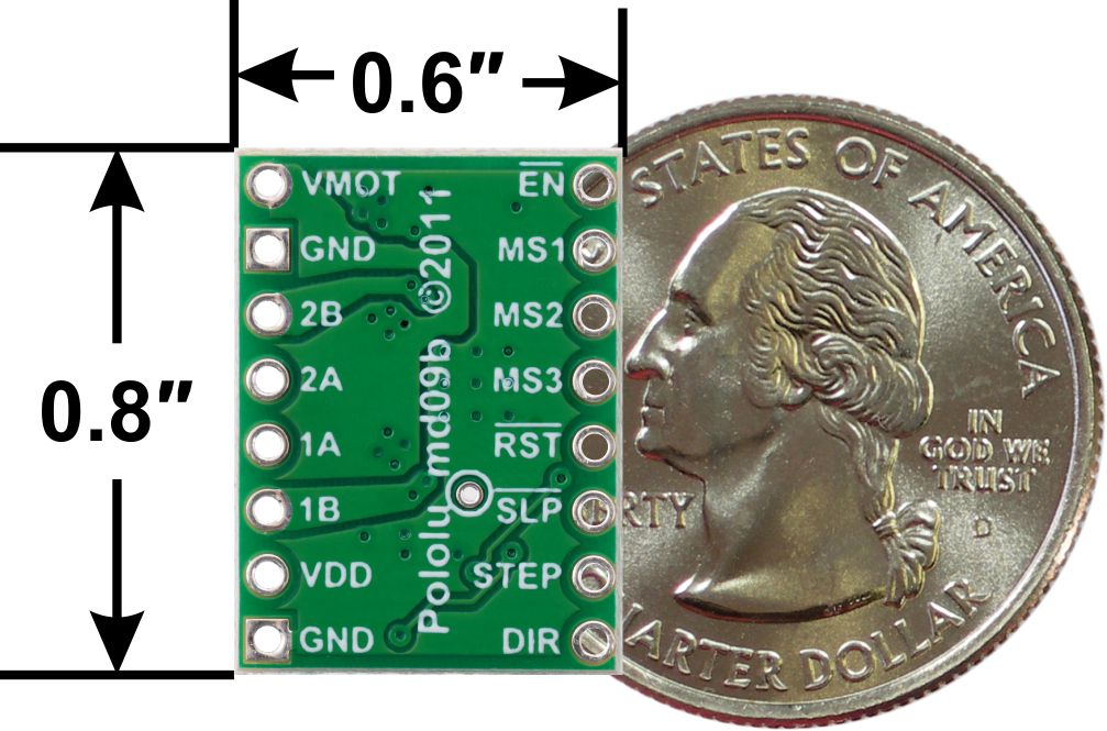
A4983/A4988 stepper motor driver carrier with dimensions.
Using the driver
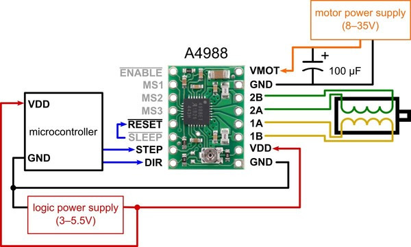
Minimal wiring diagram for connecting a microcontroller to an A4988 stepper motor driver carrier (full-step mode).
Power connections
The driver requires a logic supply voltage (3 – 5.5 V) to be connected across the VDD and GND pins and a motor supply voltage (8 – 35 V) to be connected across VMOT and GND. These supplies should have appropriate decoupling capacitors close to the board, and they should be capable of delivering the expected currents (peaks up to 4 A for the motor supply).
Motor connections
Four, six, and eight-wire stepper motors can be driven by the A4988 if they are properly connected.
Warning: Connecting or disconnecting a stepper motor while the driver is powered can destroy the driver. (More generally, rewiring anything while it is powered is asking for trouble.)
Step (and microstep) size
Stepper motors typically have a step size specification (e.g. 1.8° or 200 steps per revolution), which applies to full steps. A microstepping driver such as the A4988 allows higher resolutions by allowing intermediate step locations, which are achieved by energizing the coils with intermediate current levels. For instance, driving a motor in quarter-step mode will give the 200-step-per-revolution motor 800 microsteps per revolution by using four different current levels.
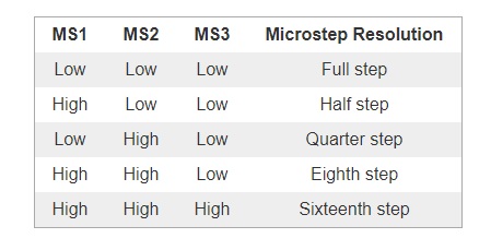
The resolution (step size) selector inputs (MS1, MS2, and MS3) enable selection from the five step resolutions according to the table below. MS1 and MS3 have internal 100kΩ pull-down resistors and MS2 has an internal 50kΩ pull-down resistor, so leaving these three microstep selection pins disconnected results in full-step mode. For the microstep modes to function correctly, the current limit must be set low enough (see below) so that current limiting gets engaged. Otherwise, the intermediate current levels will not be correctly maintained, and the motor will skip microsteps.
Control inputs
Each pulse to the STEP input corresponds to one microstep of the stepper motor in the direction selected by the DIR pin. Note that the STEP and DIR pins are not pulled to any particular voltage internally, so you should not leave either of these pins floating in your application. If you just want rotation in a single direction, you can tie DIR directly to VCC or GND. The chip has three different inputs for controlling its many power states: RST, SLP, and EN. For details about these power states, see the datasheet. Please note that the RST pin is floating; if you are not using the pin, you can connect it to the adjacent SLP pin on the PCB to bring it high and enable the board.
Current limiting
One way to maximize stepper motor performance is to use as high of a voltage as is practical for your application. In particular, increasing the voltage generally allows for higher step rates and stepping torque since the current can change more quickly in the coils after each step. However, in order to safely use voltages above the rated voltage of a stepper motor, the coil current must be actively limited to keep it from exceeding the motor’s rated current.
The A4988 supports such active current limiting, and the trimmer potentiometer on the board can be used to set the current limit. One way to set the current limit is to put the driver into full-step mode and measure the current running through a single motor coil while adjusting the current limit potentiometer. This should be done with the motor holding a fixed position (i.e. without clocking the STEP input). Note that the current you are measuring is only 70% of the actual current limit setting, since both coils are always on and limited to this value in full-step mode, so if you later enable microstepping modes, the current through the coils will be able to exceed this measured full-step current by 40% (1/0.7) on certain steps; please take this into account when using this method to set the current limit. Also, note that you will need to perform this adjustment again if you ever change the logic voltage, Vdd, since the reference voltage that sets the current limit is a function of Vdd.
Note: The coil current can be very different from the power supply current, so you should not use the current measured at the power supply to set the current limit. The appropriate place to put your current meter is in series with one of your stepper motor coils.
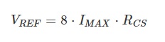
Another way to set the current limit is to calculate the reference voltage that corresponds to your desired current limit and then adjust the current limit potentiometer until you measure that voltage on the VREF pin. The VREF pin voltage is accessible on a via that is circled on the bottom silkscreen of the circuit board. The current limit, IMAX, relates to the reference voltage as follows:
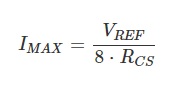
or, rearranged to solve for VREF:
RCS is the current sense resistance; original versions of this board used 0.050 Ω current sense resistors, but we switched to using 0.068 Ω current sense resistors, which makes more of the adjustment potentiometer’s range useful. The following picture shows how to identify which current sense resistors your board has:
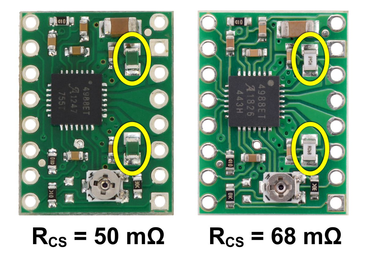
Identification of original 50 mΩ sense resistors (left) and 68 mΩ sense resistors (right).
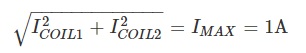
So, for example, if you want to set the current limit to 1 A and you have a board with 68 mΩ sense resistors, you would set VREF to 540 mV. Doing this ensures that even though the current through each coil changes from step to step, the magnitude of the current vector in the stepper motor stays constant at 1 A:
If you instead want the current through each coil to be 1 A in full-step mode, you would need to set the current limit to be 40% higher, or 1.4 A, since the coils are limited to approximately 70% of the set current limit in full-step mode (the equation above shows why this is the case). To do this with a board with 68 mΩ sense resistors, you would set VREF to 770 mV.
Power dissipation considerations
The A4988 driver IC has a maximum current rating of 2 A per coil, but the actual current you can deliver depends on how well you can keep the IC cool. The carrier’s printed circuit board is designed to draw heat out of the IC, but to supply more than approximately 1 A per coil, a heat sink or other cooling method is required.
This product can get hot enough to burn you long before the chip overheats. Take care when handling this product and other components connected to it.
Please note that measuring the current draw at the power supply will generally not provide an accurate measure of the coil current. Since the input voltage to the driver can be significantly higher than the coil voltage, the measured current on the power supply can be quite a bit lower than the coil current (the driver and coil basically act like a switching step-down power supply). Also, if the supply voltage is very high compared to what the motor needs to achieve the set current, the duty cycle will be very low, which also leads to significant differences between average and RMS currents.
Schematic diagram
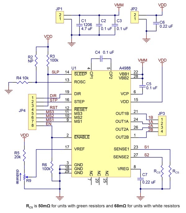
Schematic diagram of the A4988 stepper motor driver carrier (both green and black editions).
Specifications
Dimensions
| Size: | 0.6" x 0.8" |
| Weight: | 1.3 g1 |
General specifications
| Minimum operating voltage: | 8 V |
| Maximum operating voltage: | 35 V |
| Continuous current per phase: | 1 A2 |
| Maximum current per phase: | 2 A3 |
| Minimum logic voltage: | 3 V |
| Maximum logic voltage: | 5.5 V |
| Microstep resolutions: | full, 1/2, 1/4, 1/8, and 1/16 |
| Reverse voltage protection?: | N |
| Bulk packaged?: | N |
| Header pins soldered?: | N4 |
Notes:
1 Without included optional headers.
2 Without a heat sink or forced air flow.
3 With sufficient additional cooling.
4 Male header pins are included for the board's 16 holes, but they are not installed.
Don't delay, buy today.
Add to cart now!
Reviews
Customers who bought this product also bought:
-
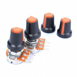
Colored...
Colored Cover for Potentiometer (Black and...
0,99 lei
-
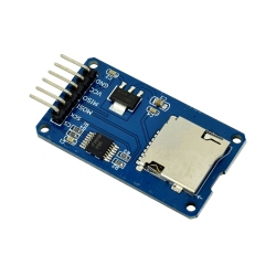
MicroSD Card...
This small SD card slot breakout board allows...
4,39 lei
-
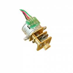
15 mm 2...
15 mm 2 Phase Stepper Motor with Metal Gearbox
39,99 lei
-
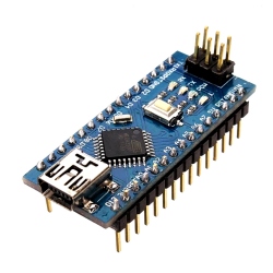
Development...
Development board compatible with the Arduino...
24,99 lei
-
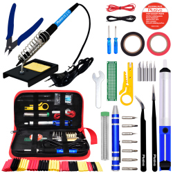
Plusivo...
Complete Soldering Kit with Diagonal Wire...
58,99 lei
-
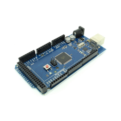
Development...
Development Board Compatible with Arduino MEGA...
92,37 lei
-
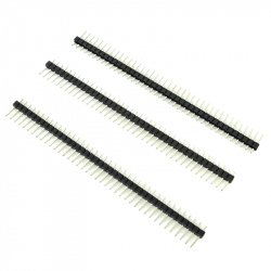
40p 2.54 mm...
This pin header is great for prototyping PCBs....
0,99 lei
-
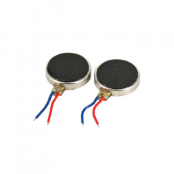
1027 Disc...
This is a small, lightweight, flat vibration...
2,49 lei
-
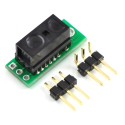
Sensor...
This small digital distance sensor detects...
49,99 lei
-
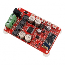
TDA7492P...
This audio amplifier is good for do-it-yourself...
103,00 lei