Dupa plasarea solicitării de comandă, in sectiunea Istoric puteti vedea cate solicitări de comandă mai avem de procesat inaintea dumneavoastra
Program de lucru: Luni - Vineri 8:30 - 17:30, pauza 12:30 - 13:30.
Se efectueaza lucrari de mentenanta la site si pot aparea erori. In cazul in care intampinati erori va rugam sa reincercati mai tarziu.
Ridicarea personala este disponibila pentru comenzile achitate in avans. Se pot ridica dupa ce sunt pregatite.
No products
 View larger


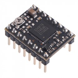
STSPIN220 Low-Voltage Stepper Motor Driver
0104110000068804
New product
This breakout board for STMicro’s STSPIN220 low-voltage microstepping bipolar stepper motor driver offers microstepping down to 1/256-step and operates from 1.8 V to 10 V, allowing stepper motors to be powered with voltages that are too low for other drivers. It can deliver up to approximately 1.1 A per phase continuously without a heat sink or forced air flow (up to 1.3 A peak). The module has a pinout and interface that are very similar to that of our popular A4988 carriers, so it can be used as a drop-in replacement for those boards in many applications.
See description for more details about the product.
Add to cart now!
This product is no longer in stock
- Write a review
- Remove this product from my favorite's list.
- Add this product to my list of favorites.
More info
Overview
This product is a carrier board or breakout board for the STSPIN220 low-voltage stepper motor driver from STMicroelectronics (ST); we therefore recommend careful reading of the STSPIN220 datasheet (1MB pdf) before using this product. This stepper motor driver offers microstep resolutions down to 1/256 of a step, and it lets you control one bipolar stepper motor at up to approximately 1.1 A per phase continuously without a heat sink or forced air flow (see the Power dissipation considerations section below for more information). Here are some of the driver’s key features:
• Simple step and direction control interface
• Nine different step resolutions down to 256 microsteps: full-step, half-step, 1/4-step, 1/8-step, 1/16-step, 1/32-step, 1/64-step, 1/128-step, and 1/256-step
• Adjustable current control lets you set the maximum current output, which lets you use voltages above your stepper motor’s rated voltage to achieve higher step rates
• Motor supply voltage: 1.8 V to 10 V (for a higher-voltage alternative, consider the STSPIN820 carrier, which operates from 7 V to 45 V)
• Can deliver 1.1 A per phase continuously without additional cooling
• Can interface directly with 3.3 V and 5 V systems
• Over-temperature thermal shutdown, over-current shutdown, and short circuit protection
• 4-layer, 2 oz copper PCB for improved heat dissipation
• Exposed solderable ground pad below the driver IC on the bottom of the PCB
• Module size, pinout, and interface match those of our A4988 stepper motor driver carriers in most respects
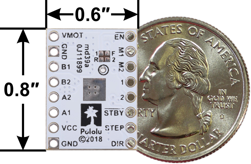
STSPIN220 Low-Voltage Stepper Motor Driver Carrier, bottom view with dimensions.
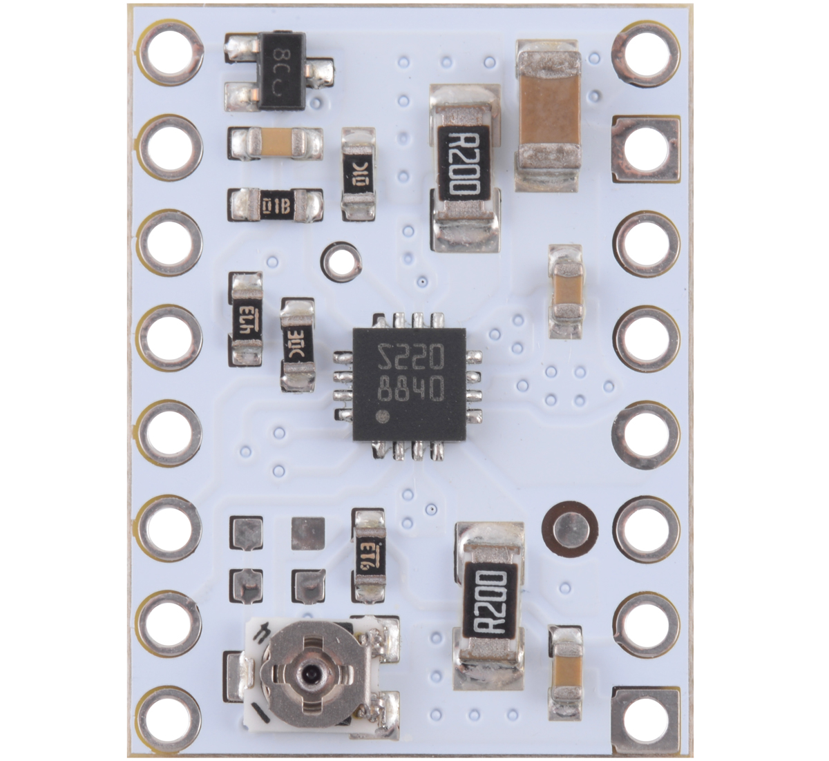
This product ships with all surface-mount components—including the STSPIN220 driver IC—installed as shown in the product picture.
Using the driver
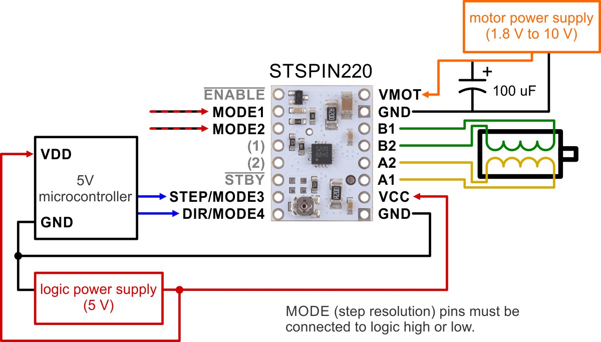
Minimal wiring diagram for connecting a microcontroller to a STSPIN220 low-voltage stepper motor driver carrier.
Power connections
The driver requires a logic supply voltage (3 – 5 V) to be connected across the VCC and GND pins and a motor supply voltage of 1.8 V to 10 V to be connected across VIN and GND. These supplies should have appropriate decoupling capacitors close to the board, and they should be capable of delivering the expected currents (peaks up to 3 A for the motor supply).
Motor connections
The STSPIN220 is intended to control a single bipolar stepper motor. The two sides of one coil should be connected across OUTA1 and OUTA2, and the two sides of the other coil should be connected across OUTB1 and OUTB2.
Warning: Connecting or disconnecting a stepper motor while the driver is powered can destroy the driver. (More generally, rewiring anything while it is powered is asking for trouble.)
Step (and microstep) size
Stepper motors typically have a step size specification (e.g. 1.8° or 200 steps per revolution), which applies to full steps. A microstepping driver such as the STSPIN220 allows higher resolutions by allowing intermediate step locations, which are achieved by energizing the coils with intermediate current levels. For instance, driving a motor in quarter-step mode will give the 200-step-per-revolution motor 800 microsteps per revolution by using four different current levels.
Unlike our other stepper motor drivers, some of the resolution (step size) selector inputs share pins with the STEP/STCK and DIR pins, and the values of the inputs are latched at power-up or when standby mode is released. After this, the values on the inputs do not affect the microstep mode, and the MODE3 and MODE4 inputs start operating as step and direction controls. The only exception is the case where MODE1 and MODE2 are both driven low, which overrides the latched microstep setting and forces the driver into full-step mode. The previous microstep setting is restored once MODE1 or MODE2 is set high.
There are nine step resolutions available as shown in the table below. The four MODE pins are floating, so they must be connected to logic high or low before operating the driver. For the microstep modes to function correctly, the current limit must be set low enough (see below) so that current limiting gets engaged. Otherwise, the intermediate current levels will not be correctly maintained, and the motor will skip microsteps.
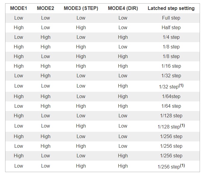
1 Keeping the MODE1 and MODE2 inputs low after the step resolution configuration forces the driver into full-step mode instead of the selected configuration.
Control inputs and status outputs
The rising edge of each pulse to the STEP (STCK) input corresponds to one microstep of the stepper motor in the direction selected by the DIR pin. Unlike most of our other stepper motor driver carriers, the STEP and DIR inputs are floating, so they must be connected to logic high or low to ensure proper operation.
The STSPIN220 IC has two different inputs for controlling its power states, STBY/RESET and EN/FAULT:
• When the STBY pin is driven low, the driver enters a low-power mode, disables the motor outputs, and resets the translation table. We call this pin STBY on our board based on the logic of how it works, but it is a direct connection to the STBY pin on the driver. The board pulls this pin high by default.
• The EN pin is inverted by our carrier board and presented as ENABLE, which makes it the same way as the enable pins on our various other stepper motor drivers with this form factor. It is pulled low on the board to enable the driver by default, and it can be driven low to disable the outputs.
The STSPIN220 can detect several fault (error) states that it reports by driving its EN/FAULT pin low. The FAULT pin is not made available by default (to avoid conflicts when using the STSPIN220 carrier as a drop-in replacement for our other stepper motor driver carriers), but it can be connected to the pin labeled "(1)" or "(2)" by bridging the surface mount jumper labeled "F" on the bottom side of the board to the corresponding pad labeled "1" or "2".
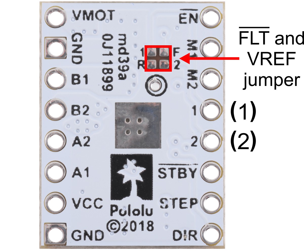
Jumpers for FLT and VREF pins on the STSPIN220 low-voltage stepper driver carrier.
Current limiting
To achieve high step rates, the motor supply is typically higher than would be permissible without active current limiting. For instance, a typical stepper motor might have a maximum current rating of 1 A with a 5 Ω coil resistance, which would indicate a maximum motor supply of 5 V. Using such a motor with 10 V would allow higher step rates, but the current must actively be limited to under 1 A to prevent damage to the motor.
The STSPIN220 supports such active current limiting, and the trimmer potentiometer on the board can be used to set the current limit. You will typically want to set the driver’s current limit to be at or below the current rating of your stepper motor. One way to set the current limit is to put the driver into full-step mode and to measure the current running through a single motor coil without clocking the STEP input. The measured current will be equal to the current limit (since both coils are always on and limited to 100% of the current limit setting in full-step mode).
Another way to set the current limit is to measure the VREF voltage and calculate the resulting current limit. The VREF pin voltage is accessible via a small hole that is circled on the bottom silkscreen of the circuit board. The current limit relates to VREF as follows:
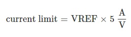
Like the FAULT pin, VREF can be connected to the pin labeled "(1)" or "(2)" by bridging the surface mount jumper labeled "R" on the bottom side of the board to the corresponding pad labeled "1" or "2".
Note: The coil current can be very different from the power supply current, so you should not use the current measured at the power supply to set the current limit. The appropriate place to put your current meter is in series with one of your stepper motor coils. If the driver is in full-step mode, both coils will always be on and limited to 100% of the current limit setting as (unlike some other drivers that limit it to about 70% in full-step mode). If your driver is in one of the microstepping modes, the current through the coils will change with each step, ranging from 0% to 100% of the set limit.
Power dissipation considerations
The driver ICs have maximum current ratings higher than the continuous currents we specify for these carrier boards, but the actual current you can deliver depends on how well you can keep the IC cool. The carrier’s printed circuit board is designed to draw heat out of the IC, but to supply more than the specified continuous current per coil, a heat sink or other cooling method is required.
This product can get hot enough to burn you long before the chip overheats. Take care when handling this product and other components connected to it.
Please note that measuring the current draw at the power supply will generally not provide an accurate measure of the coil current. Since the input voltage to the driver can be significantly higher than the coil voltage, the measured current on the power supply can be quite a bit lower than the coil current (the driver and coil basically act like a switching step-down power supply). Also, if the supply voltage is very high compared to what the motor needs to achieve the set current, the duty cycle will be very low, which also leads to significant differences between average and RMS currents. Additionally, please note that the coil current is a function of the set current limit, but it does not necessarily equal the current limit setting as the actual current through each coil changes with each microstep and can be further reduced if Active Gain Control is active.
Schematic diagram
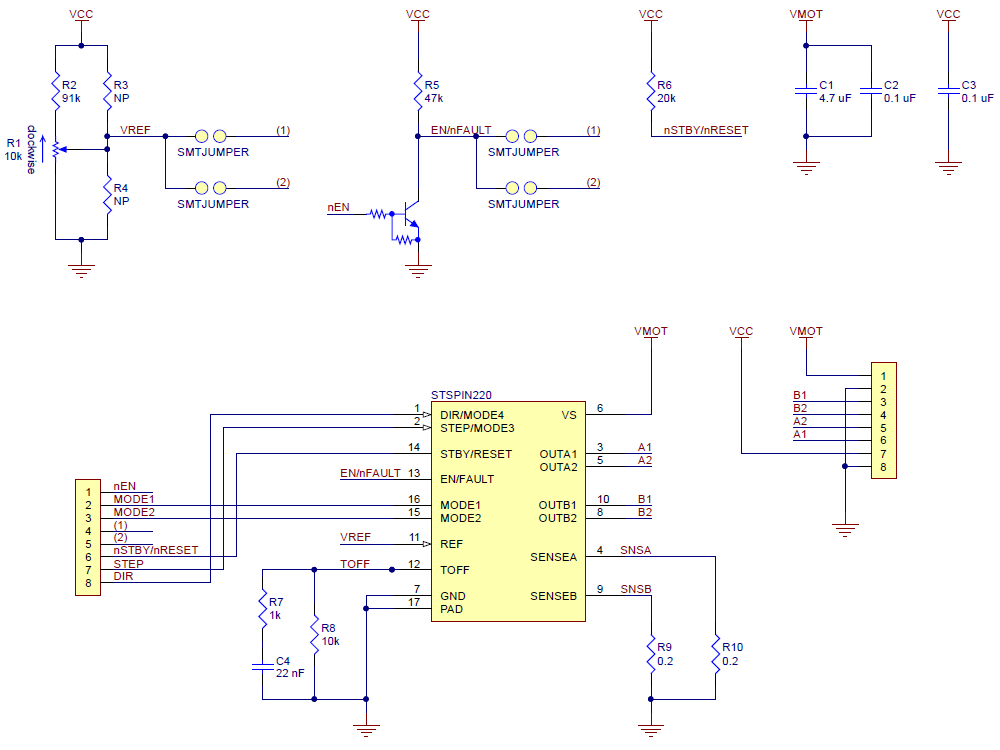
Schematic diagram of the STSPIN220 Low-Voltage Stepper Motor Driver Carrier.
This schematic is also available as a downloadable pdf (111k pdf).
Specifications
Dimensions
| Size: | 0.6" x 0.8" |
| Weight: | 1.4 g1 |
General specifications
| Motor driver: | STSPIN220 |
| Minimum operating voltage: | 1.8 V |
| Maximum operating voltage: | 10 V |
| Continuous current per phase: | 1.1 A |
| Maximum current per phase: | 1.3 A |
| Minimum logic voltage: | 1.6 V |
| Maximum logic voltage: | 5.5 V |
| Microstep resolutions: | full, 1/2, 1/4, 1/8, 1/16, 1/32, 1/64, 1/128, 1/256 |
| Current limit control: | potentiometer |
| Reverse voltage protection?: | N |
| Header pins soldered?: | N |
Notes:
1 Without included optional headers.
Don't delay, buy today.
Add to cart now!
Reviews
Customers who bought this product also bought:
-
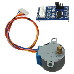
ULN2003...
This product contains a 5 V stepper motor and a...
$4.07
-
Raspberry Pi...
See description for more details about the...
$1.18
-
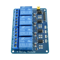
Blue...
This optoisolated 4 relay module is used for...
$3.33
-
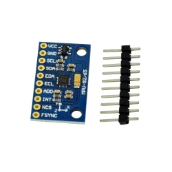
MPU6500...
This MPU6500 module integrates a 3-axis...
$4.80
-
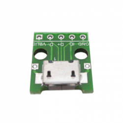
USB Micro...
The micro usb adapter module used to connect...
$0.41
-
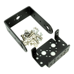
Steering...
Device Routing actuators MG995 and MG996. With...
$4.07
-
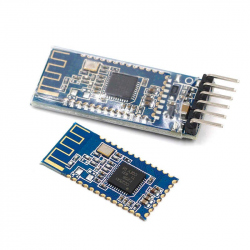
4.0...
This bluetooth module is suitable for your...
$7.20
-
TB67S249FTG...
This version of our TB67S249FTG Stepper Motor...
$30.96
-
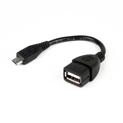
USB OTG Cable
USB OTG Cable See description for more details...
$0.96
-
1.75 mm, 1...
You can easily print with this PLA filament and...
$16.80